


Details
Additional Features
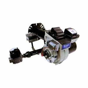
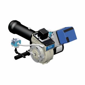
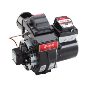
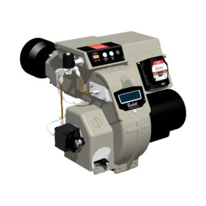
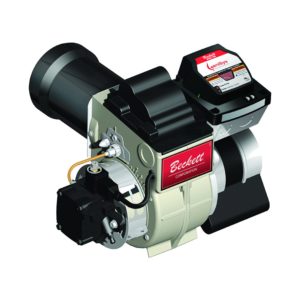
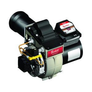
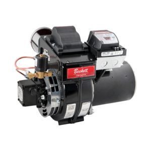
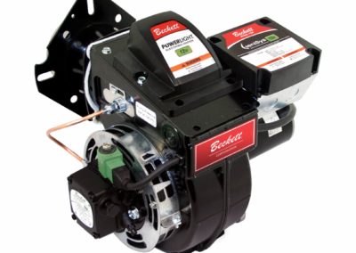
Our CG4 series chassis coupled with a welded insertion make a perfect match to your appliance. Performance-enhancing combustion technology utilizing proven fixed-head burner design.
- 24 volt gas valve, 3.5″ W.C. manifold
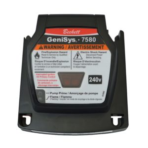
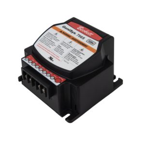
- New Beckett GeniSys™ 7590 advanced gas burner control with flame rod and air proving
- New Beckett gas igniter
- Proven Beckett fixed head combustion
- Easy access to orifice for rate change and propane conversion
- Air guide provides high static pressure for smooth starts and minimal pulsation
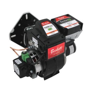
- Removable gas gun assembly for ease of servicing
Dimensions

Combustion Chamber Dimensions

| Minimum Inside Dimensions (inches) | |||||
| Firing Rate MBH | Rectangular | Horizontal Cylinder I. D. |
Length ‘L’ | Floor to Tube ‘A’ | |
| Width ‘W’ | Height ‘H’ | ||||
| 80 | 8 | 8 | 9 | 13 | 4 |
| 105 | 9 | 9 | 10 | 13.5 | 4.5 |
| 140 | 10.5 | 10.5 | 12 | 14 | 5.3 |
| 175 | 11.5 | 11.5 | 13 | 14.5 | 5.8 |
| 210 | 13 | 13 | 14.5 | 15 | 6.5 |
| 250 | 15 | 15 | 16 | 16 | 7.5 |
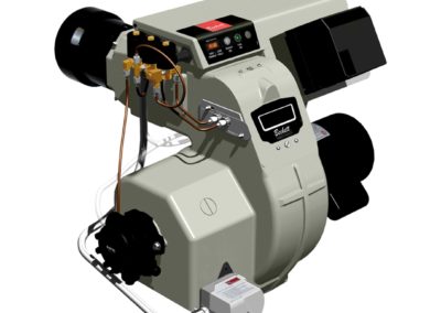
Gas Train Assembly

Removable Gun Assembly

Rate Setting Orifice

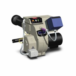
Installation of Beckett CG4 Gas Burner
Specifications
Input Firing Range*: 80,000 – 250,000 BTU/hr
Firing Mode: On-Off Only
Fuel:
-
- Natural Gas: 0.64 Specific Gravity
- Gas (LP): 1.53 Specific Gravity
Required Input Gas Supply Pressure:
-
- 4.5″ WC minimum
- 14″ WC maximum
Input Voltage**: 120 Vac + 10% / -15%; 60 Hz Input
Input Current: 2.75 A (Run); 12.0 ALR
Gas Valve: 24 Vac Dual Seat with integral regulator set to 3.5” WC for both natural gas and LP
Burner Control: Beckett 7590C Direct Ignition
Flame Detection: Flame Rectification
Igniter: Beckett 7474001 Gas Igniter
Motor: 120V PSC 1/7 HP, 3,450 RPM
Combustion Air Proving: Differential Pressure Switch
Weight: 55 lbs.
Mounting Orientation: Up to 90° from upright with motor shaft horizontal
Dimensions: 10.3″ x 13.1” x 15.8”
Air Tube Diameter: 4″
Acceptable Ambient Temperature Range: -40˚F to 150˚F
Acceptable Ambient Humidity: 5% – 95% RH non-condensing
* For altitudes higher than 2,000 feet, derate the burner capacity 4% for each 1,000 feet above sea level.
** This burner is not approved for use in 50 Hz applications.
Fire Rates & Configurations
| Firing Rate (BTU/Hr.) 1 |
Fuel Orifices | Air Tube Components 4 | Chassis Components 5 |
Initial Settings 6 |
|||||
| Natural Gas Orifice Diameter (inches) 2 |
LP Orifice Diameter (inches) 3 |
Burner Head | Nozzle P/N Suffix | Static Plate | Baffle | Band | Shutter | Band | |
| 80000 | 0.219 | 0.166 | F3G | 1 | 32910-001 | 5880 | Blank | 2½ | Blank |
| 90000 | 0.234 | 0.177 | F3G | 1 | 32910-001 | 5880 | Blank | 4 | Blank |
| 100000 | 0.25 | 0.189 | F3G | 1 | 32910-001 | 5880 | Blank | 5½ | Blank |
| 110000 | 0.277 | 0.206 | F3G | 1 | 32910-001 | 5880 | Blank | 7½ | Blank |
| 120000 | 0.316 | 0.219 | F3G | 1 | 32910-001 | 5880 | 4-slot | 9 | 0 |
| 130000 | 0.364 | 0.234 | F3G | 1 | 32910-001 | N/A | 4-slot | 5½ | 0 |
| 140000 | N/A | 0.242 | F3G | 1 | 32910-001 | N/A | 4-slot | 7½ | 0 |
| 130000 | 0.281 | 0.217 | F4G | 2 | 32910-001 | 5880 | 4-slot | 8 | 0 |
| 145000 | 0.316 | 0.234 | F4G | 2 | 32910-001 | 5880 | 4-slot | 10 | 0 |
| 160000 | 0.348 | 0.246 | F4G | 2 | 32910-001 | N/A | 4-slot | 6½ | 0 |
| 175000 | 0.406 | 0.261 | F4G | 2 | 32910-001 | N/A | 4-slot | 8½ | 0 |
| 190000 | N/A | 0.281 | F4G | 2 | 32910-001 | N/A | 4-slot | 10 | 0 |
| 180000 | 0.332 | 0.246 | F6G | 3 | N/A | N/A | 4-slot | 5½ | 0 |
| 190000 | 0.354 | 0.256 | F6G | 3 | N/A | N/A | 4-slot | 7 | 0 |
| 205000 | 0.377 | 0.266 | F6G | 3 | N/A | N/A | 4-slot | 8½ | 0 |
| 220000 | 0.422 | 0.281 | F6G | 3 | N/A | N/A | 4-slot | 10 | 0 |
| 235000 | 0.484 | 0.295 | F6G | 3 | N/A | N/A | 4-slot | 10 | 2 |
| 250000 | N/A | 0.312 | F6G | 3 | N/A | N/A | 4-slot | 10 | 4 |
1. Firing rates are based on a 3.5″ WC manifold gas pressure and use of the appropriate orifice for the fuel being fired.
2. Air tube assemblies are provided with a full selection of the natural gas orifices appropriate to the burner head.
3. LP orifices are provided in kits containing all the LP orifices for the burner head size. Kit P/N 52309-004 is for use with the F3G head, 52309-005 is for the F4G and 52309-006 is for the F6G. The installer is responsible for selecting and installing the appropriate orifice for the applications.
4 .Burner heads and nozzles are identified with the markings shown to assure the use of compatible combinations.
5. Burner chassis are built for the highest rate configuration. The installer is responsible to add the baffle and/or change the band as required for the application.
6. Initial settings are intended for use only as a starting point for burner adjustments. They cannot make provision for all installation possibilities. It is important that you adjust your burner to your installation requirements using properly calibrated flue gas analysis instruments.
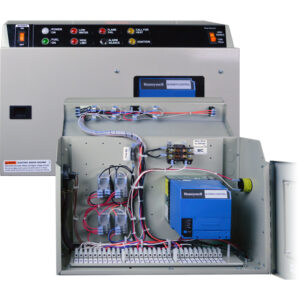
Commercial Burner Control Panels
Our heavy duty 16-gauge steel control boxes can be mounted on any of our commercial CF & CG Series burners. They come in 2 convenient sizes (12″ x 12″, 16″ x 12″) according to your burner needs. We have a variety of light indicators, voltage configurations, and other options to chose from.

Downloads & Links


Warranty
Please note, all warranty claims must be initiated through an authorized Beckett supplier/distributor. Distribution policies will not allow Beckett to directly handle warranty claims with installers and/or consumers.