


Instructions for Use
Tools & Materials Needed:
-
Screwdriver (phillips)
-
Pliers (for spring clamps)
-
5/16″ hex head driver (for hex screws that attach bracket to housing)
-
3/16″ allen key (to remove plug from housing)
-
Utility knife to cut tubing as needed
-
Safety equipment (gloves, safety glasses)
Safety Precautions:
- Turn off power: Before starting, ensure the power supply to the oil burner is switched off at the breaker.
- Verify power is off: Use a multimeter to confirm the power is off.
- Use Personal Protective Equipment (PPE): Wear gloves and safety glasses.
- Do not over-tighten to avoid damaging components or stripping threads.
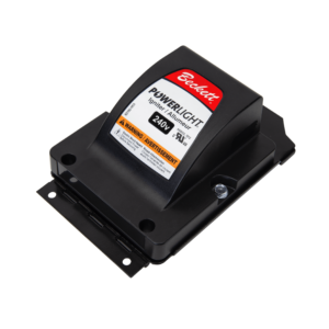
Step 1:
Mounting the Air Proving Switch
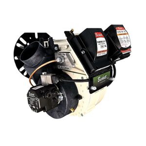
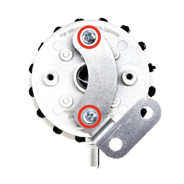
- Mount the Switch: Attach the air proving switch to the bracket using the two (phillips head) screws provided in the kit (See Figure 1).
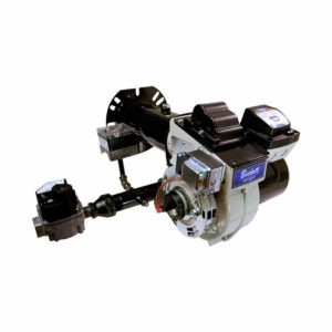
- >Attach Bracket to Housing: Use the provided two (5/16” hex head) screws to secure the bracket to the burner housing (See Figure 2). Make sure to align the bracket correctly before tightening the screws.


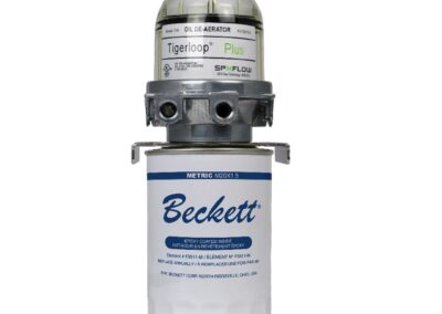
Step 2:
Install Hose Barb and Run the Hose
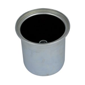
- Remove Housing Plug: Remove the housing plug (3/16” allen key).
- Thread in Hose Barb: Thread the plastic hose barb into the housing where the plug was removed. Use care not to over torque or cross thread.
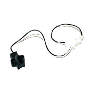
- Connect Hose to Switch: Attach one end of the hose to the barb. Cut hose to desired length (utility knife). Use spring clamps to secure the hose at both the barb and the high-pressure black connection on the switch (See Figure 3).

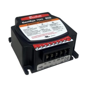
Step 3:
Electrical Connections
- Connect Wires to the Switch: Identify the two terminals on the air proving switch and attach straight receptacles on supplied wires (See Figure 4).
- Connect Wires to Control: Attach fork terminals to the “AIR” terminals on the front of the control. Ensure all connections are secure (See Figure 5).


Step 4:
Enable Air Proving
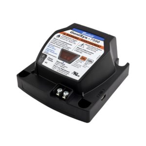
- Program Control: Using the myTechnician® App, access the control of the burner and turn on the 24 VAC air-proving feature (See Figure 6). (If needed, refer to the GeniSys® 7565 120V Advanced Oil Burner Control manual for detailed instructions).

Step 5:
Test and Validate Installation
- Run Test Cycles: Power on the system and run several burner cycles.
- Test Proper Functionality: During operation, briefly disconnect the hose to ensure that the air proving switch responds correctly by shutting down the burner(See Figure 7).If your application does not reach 0.50″ WC, use kit 52683-002 (0.25″ WC).

Step 6:
Reattach Hose and Run the Burner
- Reattach Hose: Ensure that hose connections are secure after testing (See Figure 8).
- Monitor Operation: Over the next few burner cycles, observe the system to confirm that it continues to operate consistently.

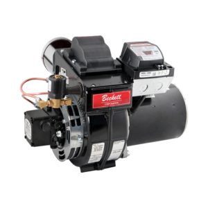
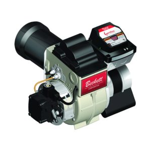
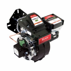
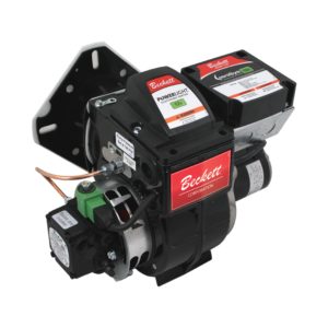
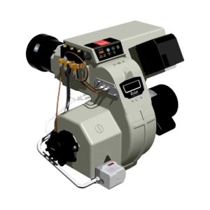
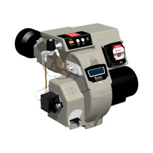
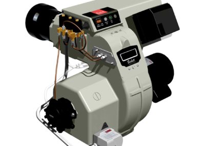
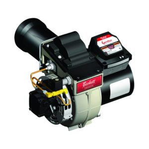
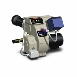
The Beckett RF Oil, Biodiesel, and Renewable Diesel Burner | 0.38 to 1.75 GPH | AC Power

As technology has advanced, so have our burners and components. The Beckett RF Burner embodies this evolution, providing you with efficiency and peace of mind. Each unit comes with a 5-year factory warranty, guaranteeing long-term reliability and value.
Upgrade to the Beckett RF burner today and experience the perfect blend of cutting-edge technology, unmatched reliability and environmental responsibility. Take the next step in reducing your carbon footprint without compromising on performance.

Downloads & Links
Manuals & Product Sheets

Warnings (prop65)
Warranty
Please note, all warranty claims must be initiated through an authorized Beckett supplier/distributor. Distribution policies will not allow Beckett to directly handle warranty claims with installers and/or consumers.
