To provide you with adequate information on solving delayed ignition problems, we need more than one bulletin. Therefore, this bulletin will consider first the electrical factors involved. The February bulletin will consider all other causes.
Delayed ignition problems can be difficult to solve. There are many possible factors making the problem rather complex. So, first let us consider the essential requirements for good ignition and then discuss some troubles that can develop.
How the Burner Ignition System Functions
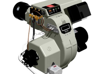
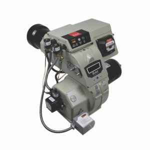
A burner that is operating correctly combines the functions of several components in order to provide prompt, dependable ignition. These steps are:
- The room thermostat calls for heat activating the primary relay coil.
- Line voltage is delivered to the motor and to the primary of the ignition transformer through the relay contacts.
- The transformer steps up the voltage to 10,000 volts in the transformer secondary.
- From the secondary terminals, contacts apply high voltage to the metal electrode rods, which are insulated from ground by porcelain insulators.
- The two electrodes are positioned parallel with a preset air gap between their tips.
- The burner blower fan creates air velocity between the electrode tips. An intense arc is established as 10,000 volts jump the air gap between electrodes.
- The forward air velocity causes the arc to loop out into a sharp “V” pattern. This helps position the heat energy required to vaporize and ignite minute oil droplets sprayed from the nozzle.
- The energy released by the burning vapors radiates upon other droplets until rapid flame propagation has established a visible flame envelope.
All these steps happen instantly.
Troubleshooting the Ignition System
When delayed ignition occurs, the ignition system is usually the first suspect. Using the sequence established above, here’s how to examine the various components.
- Start the burner and measure the supply voltage that is delivered to the transformer. Attach meter probes to the primary/transformer lead junction and the Neutral line connection. There should be a nominal 120 volts AC. If this voltage is low, measure the input to the primary control for comparison. The voltage should be approximately the same. If not, then the relay contacts are defective. Reduced input to the transformer primary will reduce the secondary output voltage which could lead to a weak ignition arc and create delayed ignition or puff-backs.
- If input is adequate, then check the output with a high voltage transformer test meter. There should be approximately 10,000 VAC (open circuit) whenever the transformer is energized.
- During the above test, examine the condition of the porcelain bushings surrounding the secondary terminals. They should be clean, free from carbon, oil, dirt, pinholes, crazing, moisture and evidence of over-the-surface arc tracking, to prevent short circuiting with the metal base.
- When the transformer is in the closed position, make sure the secondary contact springs engage the electrode rods compressing slightly for positive connection. Poor contact can cause arcing and keep the transformer from producing an adequate ignition arc at the electrode tips.
 The electrode porcelain insulators must be examined next. These also must be free from carbon, oil, dirt, pinhole leaks, crazing, cracks, moisture and evidence of over-the-surface arc tracking. Otherwise, short circuiting could cause ignition problems.
- Finally, check the electrode tips to see if they are in good condition. Any eroding can make the gap too wide. Replace any defective, worn or eroded electrodes. Look for evidence of carbon bridging due to oil spray impingement. Position them to manufacturer’s specifications. Setting the electrodes too far forward of the nozzle face, could cause grounding to the combustion head, or the arc may jump to the head. Also, be sure that the burner “Z” dimension is properly set so that the nozzle face is set back properly from the combustion head flat surface. If the electrodes are set to the manufacturer’s specifications, the proper “Z” dimension will adequately position the electrodes from the combustion head.
If the source of the delayed ignition has not been found by now, then the trouble is most likely within the oil delivery system or with improper burner adjustment. We will consider these factors in our next technical bulletin. In the meantime, this chart can be used as a handy reference guide for checking out delayed ignition problems.