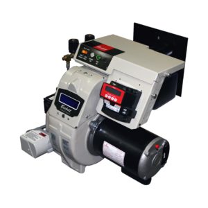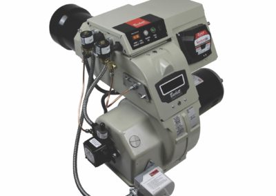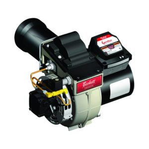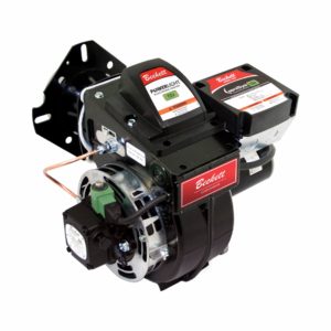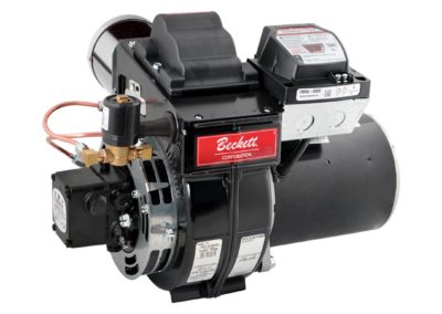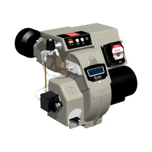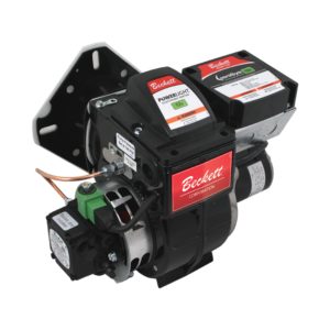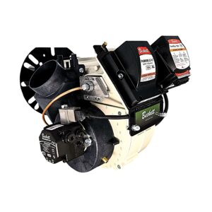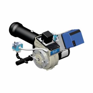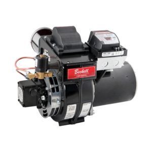
The Beckett SF oil burner uses many of the design features of the popular AF burner for high efficiency over a broad firing range. Both burners ...

To position the electrode tips in front of the face of the nozzle and above the center line, select one of two cross marks for the burners as shown in either Figure 2 or 3. Set one tip to the gauge position then adjust the other to match. Electrode tip setting reference chart is shown below. (See individual instruction manuals for more details.)
| Burner Model (Heads) | Electrode Tip Gap | Tip Height Above Nozzle Centerline | Tip Forward of Nozzle Face |
| RF, NX | 5/32″ | 1/4″ | 3/32″ |
| Standard AFG – (F, L, V), AF -(F), AFII – (FBX) | 5/32″ | 5/16″ | 1/16″ |
| AFII – (HLX, AF2) | 5/32″ | 1/4″ | 3/32″ |
| *Alternate AFG – (L & V Heads) | 5/32″ | 1/4″ | 1/8″ |
* Application specific. Not shown on T501 Gauge.

Figure 1. (Click to view larger)

Figure 2. (Click to view larger)
F, FBX, L and V head settings are set by aligning the electrode tip with the 5/16″ cross marks (Figure 2). After setting proceed to ‘Tip Gap Spacing’, Figure 4.
Note: Be careful not to scratch the nozzle face.

Figure 3. (Click to view larger)
Set the RF, NX, HLX or AF2 tip positions by aligning the electrode tip with the mark shown in Figure 3.
Set the electrode tip gap spacing (5/32″) by adjusting the tips to meet the two outside marks shown in Figure 4. Make sure the tips are centered above the nozzle by maintaining the center mark of the gauge directly above the nozzle centerline. (Also see Figure 1.)

Figure 4. (Click to view larger)
To check that the nozzle is approximately centered with the head inside diameter on FBX and F heads place gauge in head and note the gauge center mark location with respect to the nozzle center. Rotate the gauge and check several positions. For RF, NX, HLX, AF2, L and V heads, align the edge of the gauge with the inside diameter of the head and note the location of the gauge center mark with respect to the center of the nozzle. See Figures 5a and 5b.

Figure 5a. (Click to view larger)

Figure 5b. (Click to view larger)
The “Z” or zero dimension is important because it locates the nozzle for the precise relationship with the combustion head. To set the “Z” dimension for FBX and F heads, position the gauge as shown in Figure 6 and loosen the nozzle line electrode assembly so that it can be moved forward or backward in the air tube until the nozzle becomes flush against the gauge. Tighten the nozzle line escutcheon plate screw to lock this “Z” dimension securely.

Figure 6. (Click to view larger)

Figure 7. (Click to view larger)
To set the HLX or AF2 nozzle-to-head position loosen the set screw allowing the head assembly to be moved forward and backward. Set the gauge against head as shown in Figure 7. Move the head assembly until it makes contact with the nozzle face and tighten set screw.

Figure 8. (Click to view larger)
For L heads with straight shroud, set the “Z” dimension (1-3/8″) by placing the gauge edge on the leading edge of the head, and aligning the S pointer mark with the end of the straight shroud.
For L heads with conic shroud, set the “Z” dimension (1-3/4″) by placing the gauge edge on the leading edge of the head, and aligning the C pointer mark with the end of the conic shroud. (See Figure 10.)
The V head utilizes a two piece adjusting plate. To set the “Z” dimension (1-3/4″), first place the adjusting plate in the 0 position and tighten the mounting screw. Loosen the acorn nut on the second plate (and the spline nut, see Figure 9), to permit free nozzle line movement. Place the gauge edge against the leading edge of the head, and align the C mark with the end of the conic shroud shown in Figure 10. Tighten the acorn nut (this will not require further adjustment). To adjust the head assembly to the desired head setting, loosen the adjusting plate screw (see Figure 9) and move the adjusting plate forward to the required setting. Check the appliance label/manual for correct settings. Tighten the adjusting plate screw and spline nut.

Figure 9. (Click to view larger)

Figure 10. (Click to view larger)

Figure 11. (Click to view larger)
This gauge can be used to check the AFII firing pin stop screw lengths (see Figure 11). To check, place the bottom edge of the firing pin head against the edge of the gauge and read the number indicated on the gauge at the end of the pin. This number should be the same as the number stamped into the head of the firing pin.

Figure 12. (Click to view larger)
This gauge can also be used to check and set the proper gap between the AFII motor and the blower wheel (0.060″) see Figure 12.
Informative and technical training resources from the leading experts in the heating industry
Have questions about our products? Looking for a solution to address a particular application? Looking to improve the overall productivity and profitability of your operation? Please don’t hesitate to reach out or schedule a no obligation, 1-on-1 consultation with a Beckett Technical Specialist — we’d love to help.
Beckett solutions are available through our network of Distributors, Independent Representatives, and Export Representatives all around the world.