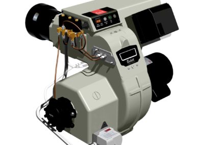
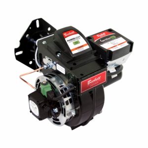
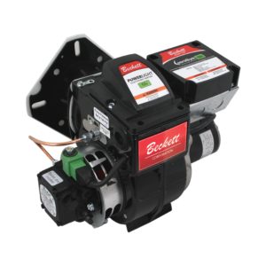
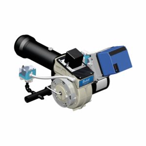
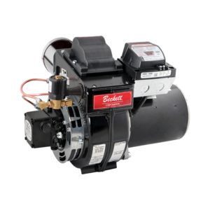
Find a Distributor

Beckett solutions are available through our network of distribution partners throughout the United States and Canada.

Find an Independent Representative

Beckett Independent Representatives provide Sales Support for our products throughout the United States and Canada.

Find an Export Representative

Beckett solutions are available for export outside of the United States and Canada through our network of Export Representatives.

Contact Us

Drop us a line with any comments or questions!

Burner Settings

(OEM Spec Guides)

Specifications for nozzles, air tube combinations, and other initial settings.

Tech Bulletins

Service bulletins and product updates.

Tutorials

Training videos and PowerPoint presentations.

Troubleshooting Guides

Solutions to common issues.

Find A Part

Look through exploded views to find the part you need.

Manuals & Guides

A library of product manuals and supplemental guides.

Product Warranty

View the limited warranty for all Beckett products.

Return Material Authorization

Submit a return material authorization (RMA) Request.

Warnings

(Proposition 65)

Frequently asked questions, and a list of affected products.

Classroom Training

Hands-on, practical installation, application, and operation training on Beckett’s latest products — in-person with the industry’s foremost authorities. Register today.

Online Training

Informative and technical training resources from the leading experts in the heating industry — now available online, on-demand, and FREE.

Product Instructional Videos

Our most popular product-related instructional / training videos for the most relevant and widely seen products and applications you’ll find in the field.

Residential Heating Solutions from Beckett®

For over 80 years Beckett products have been the number one choice of homeowners and contractors for their furnaces, boilers, and water heaters. As North America's foremost brand of burners, Beckett continues to provide industry leading design, reliability, and support. All backed by a comprehensive warranty program that ensures you will have years of trouble-free operation.

Commercial Heating/Steam Solutions from Beckett®

As North America's leading brand of burners, you can have peace of mind in using a Beckett burner on your next commercial project. With the environment in mind, we have the most comprehensive lineup of biofuel rated burners in the industry. Supported by a broad network of trained technicians, choosing a Beckett burner for your next commercial project ensures your building will have years of trouble-free operation while reducing your equipment’s impact on the environment. A return on investment for future generations.

Road Maintenance Solutions from Beckett®

When the sun is blazing and you're responsible for keeping Americas roads maintained, you'll want a burner that's as hard working as you are. Beckett's lineup of DC burners provides mobile heat for all types of road maintenance equipment. With their ease of service and parts availability from coast to coast, you can ensure the job gets done when the heat is on.

Heated Pressure Washing Solutions from Beckett®

For over 30 years Beckett has served the pressure washer market in providing rugged yet reliable burners and components for the pressure washer industry. Our compact DC powered burners provide off-grid dependable operation in the wettest of environments. All backed by a comprehensive warranty program that ensures you will have years of trouble-free operation. So, when the "pressure" is on to get a job done, you can rely on Beckett to keep you in "hot water".

Agriculture / Greenhouse Solutions from Beckett®

With a wide range of capacities, Beckett has served the needs of the agricultural industry for over 20 years. Our proven experience in the combustion field allows us to work with appliance engineers to ensure the strictest of parameters are met when drying organic products. Beckett's modular burner platform provides the most flexibility in applications while offering the most comprehensive lineup of biofuel rated burners in the industry. This ensures efficient reliable heat for future generations.

Construction Solutions from Beckett®

When freezing temperatures hit your job sites and you need dependable heat, consider Beckett for the job. From the Arctic circle to Antarctica, Beckett has proven to be the burner of choice in the harshest most remote environments. Our robust, user-friendly design provide quick maintenance and dependable operation to ensure your site stays warm.

Food Processing Solutions from Beckett®

Beckett burners and components are used in food processing applications all over the world. From bakery ovens, coffee roasters, dehydrators, and industrial process lines, Beckett robust, reliable products reduce line down time and ensure an uninterrupted output.

R.W. Beckett

From tank to flame, Beckett delivers the most technically advanced product line in the industry — burners, igniters, controls, and accessories designed to meet the performance requirements of the industry while meeting the demands of biofuels to reduce emissions and meet carbon reduction goals. Explore all that Beckett has to offer below by selecting a brand, product category, or simply filtering through the entire product offering.

Westwood by Beckett

With the acquisition of Westwood Products in 2021, Beckett added depth and diversity to its already impressive catalog. In addition to the Tigerloop suite of Oil Dearaetors which has been transitioned to our Beckett branded offering, our Westwood by Beckett product offering includes fuel filters, electrodes, tank accessories, and many other HVAC service and repair items. The line includes B100 filters which, in conjunction with the Tigerloop Bio models, completes Beckett’s industry leading suite of B100 rated components from tank-to-flame and further positions as the market leader in the drive to alternative fuels.

Residential Heating Solutions from Beckett®

For over 80 years Beckett products have been the number one choice of homeowners and contractors for their furnaces, boilers, and water heaters. As North America's foremost brand of burners, Beckett continues to provide industry leading design, reliability, and support. All backed by a comprehensive warranty program that ensures you will have years of trouble-free operation.

RF Oil Burner

RF Oil Burner

NEW! Designed to meet the many challenges of today’s modern heating appliances and process equipment, the Beckett RF oil burner is designed to ...
Commercial Heating/Steam Solutions from Beckett®

As North America's leading brand of burners, you can have peace of mind in using a Beckett burner on your next commercial project. With the environment in mind, we have the most comprehensive lineup of biofuel rated burners in the industry. Supported by a broad network of trained technicians, choosing a Beckett burner for your next commercial project ensures your building will have years of trouble-free operation while reducing your equipment’s impact on the environment. A return on investment for future generations.

Road Maintenance Solutions from Beckett®

When the sun is blazing and you're responsible for keeping Americas roads maintained, you'll want a burner that's as hard working as you are. Beckett's lineup of DC burners provides mobile heat for all types of road maintenance equipment. With their ease of service and parts availability from coast to coast, you can ensure the job gets done when the heat is on.

Heated Pressure Washing Solutions from Beckett®

For over 30 years Beckett has served the pressure washer market in providing rugged yet reliable burners and components for the pressure washer industry. Our compact DC powered burners provide off-grid dependable operation in the wettest of environments. All backed by a comprehensive warranty program that ensures you will have years of trouble-free operation. So, when the "pressure" is on to get a job done, you can rely on Beckett to keep you in "hot water".

Agriculture / Greenhouse Solutions from Beckett®

With a wide range of capacities, Beckett has served the needs of the agricultural industry for over 20 years. Our proven experience in the combustion field allows us to work with appliance engineers to ensure the strictest of parameters are met when drying organic products. Beckett's modular burner platform provides the most flexibility in applications while offering the most comprehensive lineup of biofuel rated burners in the industry. This ensures efficient reliable heat for future generations.

Construction Solutions from Beckett®

When freezing temperatures hit your job sites and you need dependable heat, consider Beckett for the job. From the Arctic circle to Antarctica, Beckett has proven to be the burner of choice in the harshest most remote environments. Our robust, user-friendly design provide quick maintenance and dependable operation to ensure your site stays warm.

Food Processing Solutions from Beckett®

Beckett burners and components are used in food processing applications all over the world. From bakery ovens, coffee roasters, dehydrators, and industrial process lines, Beckett robust, reliable products reduce line down time and ensure an uninterrupted output.

Beckett Oil Burners

R.W. Beckett oil-fired burners were created with customer satisfaction and sustainability in mind. Our utilization of advanced components results in higher efficiency and reliability, all while reducing carbon emissions.

Our burners are suitable for a multitude of needs. They are certified for firing traditional heating oils, biodiesel blends (B20), and renewable diesel blends (R95). Truly versatile, our burners are available in AC and DC voltages and in capacities from 0.40 to 35.0 GPH. Applicable uses range from residential homes to commercial buildings, for both industrial and process installations, R.W. Beckett can meet your demands. After installation our proven burners provide years of reliable service with strong and accessible technical support.

Beckett Gas Burners

R.W. Beckett gas-fired burners were created with customer satisfaction and sustainability in mind. Our utilization of advanced components results in higher efficiency, reliability, and accessibility, all while reducing carbon emissions.

Available in capacities ranging from 250 to 5,000 MBH, our burners are suitable for a multitude of needs. Applicable uses range from residential homes to commercial, for both industrial and process installations, R.W. Beckett can meet your demands. Our burners are easy to install and service, engineered to provide years of reliable service, and backed by solid technical support and fast delivery.

Beckett GeniSys® Burner Primary Safety Controls

R.W. Beckett’s burner controls were created with customer satisfaction and safety in mind. Our entire suite of burner controls utilizes the most current technology to safely control the combustion process.

Available in both AC and DC voltages for off-grid applications, our controls are suitable for a multitude of needs. Our new GeniSys® model 7565 Advanced Burner Control is compatible with the myTechnician™ app for modernized accessibility. The app assists with diagnostics, troubleshooting, and more. With applicable uses of our controls ranging from residential homes to commercial buildings, to process applications R.W. Beckett can meet your demands. Our multitude of models offer both fixed and programmable options and serve as a direct replacement for many competitive combustion controls.

Beckett AquaSmart® Boiler Safety Controls

R.W. Beckett’s boiler controls were created with customer satisfaction and sustainability in mind. The boiler control was built using Beckett’s proprietary HeatManager® algorithm which saves fuel by minimizing operating temperature, reducing energy consumption without sacrificing homeowner comfort.

Applicable to both oil and gas-fired boilers, the control is convenient for any household. With our digital display and touch pad we have made for a more intuitive experience, allowing for flexible programming of temperature limits and other settings.

Control Combo

Control Combo

Upgrade to microprocessor-based burner and boiler control with 10% fuel savings guaranteed! The Beckett Aquasmart™ / GeniSys® Combination ...
Beckett Powerlight® Igniters

R.W. Beckett igniters were created with customer satisfaction and reliability in mind. Providing an advanced option for oil-fired burners, our Powerlight® igniter also serves as a universal replacement for other manufacturers’ igniters.

Available in a variety of AC and DC voltages for off-grid applications, our product is suitable for a multitude of needs. Designed for various applications, our igniter can be found in residential homes, commercial property, and even high-moisture environments.

Beckett Tigerloop® Oil Deaerators

R.W. Beckett’s oil deaerators were created with customer satisfaction and efficiency in mind. With over 30 years of fine-tuning, the Tigerloop® is the most advanced oil deaerator in the world.

With its unmatched performance, Tigerloop® can handle capacities up to 50 GPH and is compatible with different heating fuels, depending on the model. The standard model is compatible with #1 and #2 heating oil and B5 Bioheat, while the Bio model accepts biofuel blends up to B100. Catering to many needs, our oil deaerator is also a safe, economical, and environmentally friendly choice for all supply systems.

Beckett Oil Filters

Beckett branded Spin-on filters are epoxy coated, UL Listed or UL Recognized and rated from 10 to 15 microns. Commercial Spin-on filters are rated for 52 GPH, 20 PSI, and 30 Microns. The line includes a cast aluminum tops, Filter Life Indicator (FLi™) gauge and is suitable for #1 and #2 fuel oil and rated up to B100 bio-fuels.

Westwood by Beckett canister filters feature cast iron tops and epoxy coated canisters. Element options include Classic Felt, cellulose acetate, and Classic Yarn. UL Listed/Recognized canister filters exceed GPH and pressure ratings of most competitors.

Beckett Connected Devices

R.W Beckett’s internet connected products were created with customer satisfaction and accessibility in mind. With our modernized approach, these products can be remotely accessed through our mobile app or web browser.

Through the myTechnician™ mobile app, connected products come with multiple features including troubleshooting, product programming and diagnostics. With the BeckettLink® connected tank gauge system and Wi-Fi hub, end users and oil dealers can use the Beckett Dealer Dashboard to be alerted remotely if the tank drops below predetermined levels.

For your convenience, Tank Accessories has been divided into distinct categories to help you find the products you need. Please click the links below to see all the products in each of these categories.

Beckett Electrodes and Insulators

RW Beckett manufacturers hundreds of Westwood electrodes, flame rods and spark ignitors. Many are sold through distribution and additional items are available for OEM customers for special applications. RW Beckett can manufacture specialty electrodes to your specifications. The Auburn and Champion brands are also available.

All Categories

View All Products

Troubleshooting Guides

Oil Burner Guides

Commercial Guides

System Control Guides

Oil Burner Guides

AF/AFG, AFII, NX, SF/SM
CF375, CF500/800
1. Burner will not start

Symptom A:

No Lights on the GeniSys Primary Control

No power to burner

Action:Check voltage between L1 and L2 terminals. See the GeniSys Manual for details.

Additional Action:If no voltage is present, check voltage at the operating limit.


Symptom B:

The lights on the GeniSys Primary Control come on for 1 second when powered up, then turn off

Cause 1 – If this is a Boiler, limit not receiving voltage from boiler control

Action: Verify:

  1. There is a call for heat.
  2. There is a jumper wire between TW / TR.
  3. 120v is present at (L1 to L2) and (Limit to L2) of the GeniSys Primary Control.
Cause 2 – If this is a furnace, thermostats not closing the circuit

Action: Jumper TW and TR of the Primary Control. If the burner starts, then check your thermostat.

Additional Action:Also verify there is 120v at L1 to L2 and Limit to L2.


Symptom C

Flame light is on

The cad cell (flame detector) is seeing light

Action:

  1. Turn the power off to the burner. Loosen control. Verify there are not any exposed wires.
  2. Remove yellow cad cell wires from the back of the GeniSys Primary Control. Turn the power back on. The flame light should go out on the Primary Control

Additional Action: If the light remains on:

  1. Verify the cad cell is not seeing any apparent light.
  2. If the flame light remains on, replace the GeniSys Primary Control.
  3. If the light goes off, replace the cad cell (part number 7006U).

Notes: See the Cad Cell Tech Bulletin for more information.


Symptom D

Red reset button is blinking

The GeniSys Primary Control is in a soft lockout

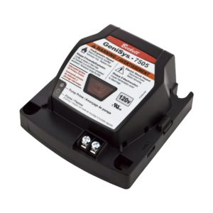
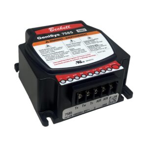
Action: Press and hold the reset button for at least one second. This will reset the control. For more in-depth GeniSys troubleshooting, visit the System Controls GeniSys Series 7505, 7575, 7580 Troubleshooting section.

Notes: The GeniSys Primary Control may lock out for:

  1. Either an unacceptable flame signal.
  2. A flame during purge cycles.
  3. Too many recycle attempts.
  4. An ideal flame signal is 1600 Ohms or less.

See the Cad Cell Tech Bulletin for more information.


Symptom E

Red reset button stays on solid

The GeniSys Primary Control is in a hard lockout

Action:The Genisys Primary Control is in a Restricted (hard) lockout This means the control has locked out 3 times.

Additional Actions:Hold the reset button down for 15 seconds. When the reset light goes out, release the button. The control will reset. For more in-depth GeniSys troubleshooting, visit the System Controls GeniSys Series 7505, 7575, 7580 Troubleshooting section.

Notes:The pump prime light will turn on solid once the button is held for 15 seconds until the button is released. Refer to your GeniSys manual for more information. To help troubleshoot the GeniSys control more effectively, use our Contractor’s Tool (Part number 52082U).

2. Burner runs, ignites, then stops

Cause 1 – Flame is present but sensor has weak or intermittent signal

Action: Check and correct flame sensing circuit (cad cell and wiring).

Notes: See the Cad Cell Tech Bulletin for more information.

Cause 2 – Burner setup out of recommended adjustments

Action: Verify burner specs.

Notes: Refer to our Residential Oil Specification Guide to see start up settings.


Cause 3 – Flame failure

Action: Check and correct:

  1. Fuel supply.
  2. Proper flue draft and chamber draft.
  3. Nozzle and air settings.
  4. See if a low firing rate baffle is required for this burner combination.
  5. Verify electrode condition and settings

Notes: Refer to our Residential Oil Specification Guide to see start up settings.

Cause 4 – Lack of retention

Action:

  1. Check chamber.
  2. Draft oil supply, 3 nozzle spec.

Notes: For more information about the Low Firing Rate Baffle (click here).

3. Nozzle Afterdrip

Cause 1 – Air entrapped in the nozzle line assembly / Air in oil supply

Action: Bleed pump, Check for air in oil supply line by putting a clear hose on the pump bleeder port.

Notes: Refer to the Nozzle Afterdrip Tech Bulletin for more information.


Cause 2 – Oil expansion in the nozzle line assembly, due to radiated heat at shutdown

Action:

  1. Lower the CO2 by increasing air settings.
  2. Put a post purge on control to remove excess heat.

Notes: Refer to the Nozzle Afterdrip Tech Bulletin for more information.


Cause 3 –

  1. A defective pump shut-off valve
  2. Solenoid stuck open
  3. Debris in solenoid

Action: Loosen 1/8″ high pressure copper line and if oil is leaking through, replace valve or pump with solenoid valve.

Notes: Refer to the Nozzle Afterdrip Tech Bulletin for more information.

4. Flue gas analysis not correct

Cause 1 – High CO
Recommended CO is less than 50 PPM, and usually 10 PPM or less. If greater, possible causes are:

  1. Excess air
  2. Improper CO2 as recommended by the appliance manufacturer
  3. Check the appliance manual for recommended CO2
  4. Heat exchanger leaks
  5. Insufficient combustion air supply

Action: Check and correct:

  1. Blocked flue, heat exchanger and chimney.
  2. Burner head and nozzle combination.
  3. Insertion depth in short furnaces.
  4. Flame impingement on damaged refractory.
  5. High draft (pulling partially burned products from the base of the flame).
  6. Cold furnace.
  7. Greatly oversized furnace.

Notes: Refer to our Residential Oil Specification Guide to see start up settings.


Cause 2 – CO2 – too high with air settings at specified opening
Also O2 – too low with air settings at specified opening

  1. Inadequate air supply to boiler room
  2. Boiler / furnace draft
  3. Firing rate is not correct

Action: Pre-set air settings are approximate for start-up. Refer to the appliance manual for recommended set-up procedure.

Notes: Refer to our Residential Oil Specification Guide to see start up settings.

5. Unable to obtain a zero smoke

Refer to our Residential Oil Specification Guide to see start up settings. Reference NFPA 31 Standard for the Installation of Oil-Burning Equipment.

Cause 1 – Not enough combustion air

Action: Check and correct:

  1. Adequate combustion air to support all equipment.
  2. Full opening of burner’s air shutter and band.
  3. Debris obstructing air shutter and band.
  4. Correct air guide or inlet.
  5. Blower wheel not tight on motor shaft, correct blower wheel adjustment.
  6. Combustion air leakage from burner.
  7. High furnace pressure.

Notes: Refer to the Combustion Air Requirements Tech Bulletin for more information.

Cause 2 – Fouled Nozzle

Action: Replace nozzle.

Notes: Refer to our Residential Oil Specification Guide to see start up settings.

Cause 3 – Air in oil supply

Action: Run a vacuum test, Use a clear hose on the pump bleeder port to see if there is air present.

Notes: Refer to the Suction Line Leaks Tech Bulletin for more information.


Cause 4 – Wrong burner specifications

Action: Refer to the Appliance manual.

Notes: Refer to our Residential Oil Specification Guide to see start up settings.

Cause 5 – Plugged heat exchanger

Action: Check chamber and breech draft.

Notes: Refer to the Appliance manufacturer for recommended draft settings.

Cause 6 – Fuel Quality

Action: Test with alternate source of fuel.

Notes: Refer to the Oil Quality Tech Bulletin for more information.

Cause 7 – Cracked heat exchanger

Action: Replace chamber.

Cause 8 – Flame impingement

Action: Check nozzle, draft and combustion chamber.

Cause 9 – Head and nozzle not correctly paired

Action: Verify your components are correct.

Notes: Refer to our Residential Oil Specification Guide to see start up settings.

6. Burner has a whining noise while running

Cause 1 – Air in the pump

Action: Check for air in the fuel supply line. Bleed the oil pump.

Additional Action: If noise persists, put on a vacuum gauge at the fuel pump’s inlet to see if there is a restriction in the oil supply line.

Notes: For additional potential causes (Click Here)

Cause 2 – Worn Motor Bearings

Action: Replace Motor.

7. Vibration of burner

Symptom A

Burner shakes whenever blower runs

Cause 1 – Issues with the Blower Wheel or Housing

Action:

  1. Check that the blower wheel is tight on the motor shaft.
  2. Check for warpage or damage to blower wheel.
  3. Make sure the motor is seated properly on the housing.
  4. Make sure motor bolts are evenly tightened.
  5. Check for debris in burner housing.
  6. Check the fit of the motor to housing and for potential damage to the housing.
  7. Check shaft alignment.
  8. Make sure the coupling is not too tight.

Notes: Refer to the burner manual for the proper gap of the blower to motor flange surface.

Commercial Guides

CG Series
1. Burner will not start
Symptom A
No lights, no blower


Cause 1 – No power to burner

Action:

Correct power supply.

Notes:

RM7800 Display Module is available for more in depth troubleshooting codes. (Part number 7542U).

Cause 2 – CG15, CG25 and CG50: Power to motor but no power to control

Action:

Wire the control as shown on the schematic (110 v control power is generally separate from high voltage motor power).

Notes:

The basic wiring schematics are located in the appropriate burner’s manual. Refer to the CG15/CG25/CG50 Burner Manual for more information.

Cause 3 – Control circuit fuse blown

Action:

Replace fuse.

Cause 4 – Flame safeguard is defective

Action:

Verify the control is receiving voltage.

Notes:

Replace flame safeguard.

Symptom B
Power light is on but no blower


Cause 1 – Limit string not completed

Action:

Trace limit string with multimeter and correct.

Notes:

Verify there is 120v to terminals L2 and 6 on the subbase of the control.

Cause 2 – Blower motor is defective

Action:

Check and correct blower motor condition.

Cause 3 – Flame safeguard is defective

Action:

Replace flame safeguard.

Symptom C
Power light and alarm light are on but no blower


Cause 1 – One of the configuration jumpers has been changed after 200 hours of operation

Action:

Replace flame safeguard.

Notes:

Examples are: Resistors JR1, JR2 and JR3.

Cause 2 – No power to blower motor

Action 1 – CG10 Burner Models:

When the limit string is complete, 120v is sent from terminal 5 of the controller subbase to the blower motor. Verify that voltage is present. If voltage is present:

  1. Verify wiring to the motor is correct.
  2. Make sure the motor spins freely.
  3. The CG10 replacement part number is 21341U.

Action 2 – CG15, CG25 and CG50 Burner Models:

When the limit string is complete, 120v is sent from terminal 5 of the controller subbase to the motor contactor coil. Verify that voltage is present. If voltage is present:

  1. Verify wiring to the motor contactor is correct.
  2. If the motor contactor is operating correctly, make sure the motor spins freely.
  3. Refer to the CG15/CG25/CG50 Burner Manual for replacement parts or Find a Part here.

Additional Action:

Is jumper JR3 of RM7897 clipped? If so, check and correct:  power supply to blower motor, control signal to starter or contactor, overload trip.

Notes:

Is JR3 intact? Burner would not have locked out.

Cause 3 – Power to ignition or fuel valve circuits before completion of purge

Action:

Check and correct ignition and fuel valve wiring, re-set flame safeguard.

Cause 4 – Flame detected during stand-by for more than 30 seconds.

Action:

Check furnace for flame or stray UV source (bright light or spark) – correct and re-set flame safeguard.
[/column][/column-group] [column-group][column]

Cause 5 – Blower motor is defective

Action:

Is jumper JR3 of RM7897 clipped?  If so, check and correct blower motor condition.  If not, burner would not have locked out.

Cause 6 – Flame safeguard purge card is defective or missing

Action:

Replace purge card, re-set flame safeguard.

Cause 7 – Low voltage/line noise/incorrect frequency

Action:

Check and correct electrical power supply, re-set flame safeguard.

Cause 8 – RM7840L Preignition interlock (proof of closure valve) is open 30 seconds

Action:

Check and correct POC switch, adjustment and wiring.  Re-set flame safeguard.

Cause 9 – RM7840L interlock check lockout

Action:

Is jumper JR3 of RM7840L clipped?  If so, check and correct all interlocks for correct status (at least one failed).  If not, this does not apply.

Cause 10 – Flame safeguard is defective

Action:

Replace flame safeguard.

2. Blower motor starts and continues running but burner will not light
Cause 1 – Airflow switch not closing

Action:

Has jumper JR3 been clipped?  If so, burner would have locked out after 10 seconds of not proving air flow.

Notes:

Is jumper JR3 Intact?  If so, burner would have locked out after 4 minutes of not proving air flow. Check and correct blower wheel, air switch sensing lines, wiring, and air switch setting.

Cause 2 – Flame safeguard run/test switch is in test position

Action:

Change switch position to run.

Notes:

This is located on the top of the 7800 Control.

Cause 3 – Flame safeguard is defective

Action:

Replace flame safeguard.

3. Blower motor starts, burner does not light, flame safeguard locks out (alarm light on)
Cause 1 – Fault in ignition circuit or a weak spark

Action:

Check and correct ignition transformer, high tension wire, electrode settings, flame safeguard ignition circuit and wiring.

Notes:

The flame establishing period is 4 seconds. If no spark is present during this period, replace the ignition transformer. Part number 51976U (CG15, CG25 and CG50). Part number 52014U (CG10).

Cause 2 – Inadequate fuel supply to burner

Action:

Check and correct manual and electric valves in gas train, gas supply to train.

Cause 3 – Flame detected during purge

Action:

Check furnace for flame or stray UV source (bright light or spark) – correct.

Cause 4 – Flame not detected within 4 seconds of energizing fuel valves

Action:

Observe the furnace for flame.  If present: check and correct flame rod or scanner, amplifier and wiring; for flame rod, verify grounding of flame rod circuit at sub-base.

Notes:

Observe the furnace for flame. If not present: check and correct fuel supply and gas train (including length from last valve to manifold), air settings, draft and blower, and ignition system and electrodes.

Cause 5 – Power to ignition or fuel valve circuits before completion of purge

Action:

Check and correct ignition and fuel valve wiring.

Cause 6 – Flame safeguard purge card is defective or missing

Action:

Replace purge card, re-set flame safeguard.

Cause 7 – Airflow switch not closed within 10 seconds

Action:

Is the control RM7840L (or RM7897 with jumper JR3 clipped)?  If so, check and correct blower wheel condition and tightness, air switch function, wiring and setting. If not, burner would not have locked out.

Cause 8 – RM7840L open damper purge circuit not proving in 4 min 15 sec.

Action:

Check and correct damper travel is unobstructed, damper motor end switch setting, wiring.

Cause 9 – RM7840L low fire start circuit not proving in 4 min 15 sec.

Action:

Check and correct damper motor end switch wiring.

Cause 10 – RM7840L preignition interlock (proof of closure valve) opens during prepurge

Action:

Check and correct POC switch, adjustment and wiring. Re-set flame safeguard.

Cause 11 – Flame safeguard is defective

Action:

Replace flame safeguard.

4. Burner runs, then stops and re-cycles
Cause 1 – Flame is present but sensor has weak or intermittent signal

Action:

Check and correct flame sensing circuit – flame rod or scanner, amplifier and wiring.  For flame rod, verify grounding of flame rod circuit at sub-base.

Cause 2 – Flame failure

Action:

Check and correct fuel supply, air damper settings, blower wheel and motor, furnace draft

Notes:

Refer to our Commercial Gas Specification Guide to see start up settings.

Cause 3 – Low voltage for less than 4 minutes

Action:

Check and correct power supply to burner.

5. Burner runs, then stops and flame safeguard locks out (alarm light on)
Cause 1 – Low voltage for more than 4 minutes

Action:

Check and correct power supply to burner, re-set flame safeguard.

Cause 2 – Power to ignition circuit during run interval

Action:

Check and correct ignition wiring, re-set flame safeguard.

Cause 3 – Flame safeguard purge card is defective or missing

Action:

Replace purge card, re-set flame safeguard.

Cause 4 – Flame failure

Action:

Is the control RM7840L or RM7897 with jumper JR2 clipped?  If so, check and correct:

  1. Flame sensing circuit – flame rod or uv scanner.
  2. For flame rod, verify grounding of flame rod circuit at sub-base. Otherwise control recycles on flame failure.


Cause 5 – Flame is present but sensor has weak or intermittent signal

Action:

Is the control RM7840L or RM7897 with jumper JR2 clipped? If so check and correct:

  1. Flame sensing circuit – flame rod or uv scanner.
  2. For flame rod, verify grounding of flame rod circuit at sub-base. Otherwise control recycles on flame failure.


Cause 6 – Airflow switch not closing

Action:

Is control RM7840L (or RM7897 with jumper JR3 clipped)?  If so, check and correct blower wheel condition and tightness, air switch function, wiring and setting. If not, burner would not have locked out.

Cause 7 – RM7840L low fire switch open during main flame establishing period

Action:

Check and correct air damper motor low fire switch and wiring, and air damper obstruction.

Cause 8 – Flame safeguard is defective

Action:

Replace flame safeguard.

6. Burner runs, then stops and locks out during postpurge (RM7840L) (alarm light on)
Cause 1 – RM7840L Preignition interlock (proof of closure valve) is open 5 seconds after run interval

Action:

Check and correct: POC switch, adjustment and wiring.  Re-set flame safeguard.

Cause 2 – Power to ignition or fuel valve circuits during postpurge

Action:

Check and correct: ignition and fuel valve wiring, re-set flame safeguard.

Cause 3 – Flame safeguard purge card is defective or missing

Action:

Replace purge card, re-set flame safeguard.

7. Burner runs at low fire rate but air damper will not go to high fire (low/high/low control)
Cause 1 – Boiler rate control wiring is in open position, preventing high fire

Action:

Trace power through rate control wiring to determine where power is lost – flame safeguard terminal – burner low fire switch – boiler rate control switch(es) – low air relay –  correct as required to power damper motor.

Cause 2 – Damper motor is powered but will not move

Action:

Check for binding in damper – replace damper motor if required.

Cause 3 – Flame safeguard terminal is not powered

Action:

Verify correct wiring, replace flame safeguard.

8. Burner runs at low fire rate and air damper goes to high fire position but fuel valves will not go to high fire position (low/high/low control)
Cause 1 – High fire fuel valve is not being powered

Action:

Trace power through fuel valve wiring to determine where power is lost – from flame safeguard to damper motor – damper motor switch – fuel valve wiring –  correct as required to power fuel valve.

Cause 2 – High fire fuel valve is powered but fuel pressure does not increase


Action:

Check high fire fuel pressure regulator setting – if it’s correct replace the high fire fuel valve.

9. Noise from burner
Cause 1 – Rubbing noise from blower wheel

Action:

Check and correct: wheel set screw tightness, wheel-to-motor plate and wheel-to-inlet guide clearances, wheel integrity.

Cause 2 – Air in-rush noise at damper

Action:

Check and correct: damper obstructions, damper blade tightness on shaft, low fire firing rate (too low causes noise).

Cause 3 – Harsh combustion noise

Action:

Check and correct: firing rate (too high causes noise), O2 level (excessive air causes noise), head setting adjustment.

Cause 4 – Combustion rumble/pulsation – continuous

Action:

Check and correct:

  1. Draft is too high (tall stack, inadequate draft controls)
  2. Excess air too high, head setting, gas spud obstruction
  3. Correct blower wheel size
  4. supply pressure to gas train (high or very low pressure drop across regulator)
  5. pressure fluctuations coming to gas train from oversized supply regulator,
  6. pressure fluctuations coming to furnace from flue stack (add a barometric)
  7. un-approved boiler application (furnace too small)
[column-group][column]
Cause 5 – Rumble or roar at light-off (Rough light-off)

Action:

Check and correct: Draft is too high (tall stack, inadequate draft controls), lightoff rate is too high (check manifold pressure at light-off), ignition electrodes are worn or incorrectly set, incorrect burner head and/or head setting, high excess air, incorrect application (furnace too small), “feedback” resonance from stack (add a barometric).

Cause 6 – “Trumpet” at lightoff

Acton:

Slight trumpet (barely audible, lasts < 5 seconds) is considered a normal condition, don’t worry about it. Pronounced trumpet – treat as rumble or roar.

Cause 7 – Alarm siren/bell

Action:

Check and correct lockout condition.

10. Odor around burner / boiler
Cause 1 – “Rotten egg” odor – gas

Acton:

DO:  Call your gas supplier from a phone outside the building and follow his instructions. Call the fire department if you cannot contact your supplier.

DO NOT touch any electrical switch, try to light any appliance, or use any phone in the building.

Cause 2 – Sharp pungent odor, burns eyes – aldehydes formed with carbon monoxide

Action:

Take corrective action gradually to avoid explosion hazard. Check for not enough air or too much gas:  inadequate air supply to boiler room, obstructed or incorrectly adjusted air inlet to burner, blocked or incorrectly adjusted stack vent, excessive gas pressure to train, seized or incorrectly adjusted gas pressure regulator.

11. Vibration of burner
Cause 1 – Blower or motor imbalance (burner shakes whenever blower runs)

Action:

Check that blower is tight on motor shaft, has no missing balance weights, no obvious damage to blower wheel.

Cause 2 – Combustion pulsation (burner shakes when burner is firing)

Action:

Check and correct: excess air level, head setting, gas spud obstruction, correct blower wheel size, supply pressure to gas train (high or very low pressure drop across regulator), pressure fluctuations coming to gas train from oversized supply regulator, pressure fluctuations coming to furnace from flue stack (add a barometric), un-approved boiler application (furnace too small).

12. Flame appearance not right
Cause 1 – Flame size – too big

Action:

Check and correct:  excess air is low (low O2 or high CO2), rate is high, operation at high elevation (flame expands in low barometric pressure), flue gas recirculation, cold furnace.

Cause 2 – Flame size – too small

Action:

Check and correct:  excess air is high (high O2 or low CO2), rate is low, furnace has a lot of refractory (re-radiated heat speeds up flame and shrinks its size).

Cause 3 – Lopsided flame – not centered in furnace

Action:

Check and correct:  burner head not centered in air tube, gas orifice obstructed, furnace flow pattern (flame drawn toward furnace outlet), furnace refractory pattern (re-radiated heat from refractory speeds up flame), flame buoyancy in furnace (greater influence in cold furnace).

Cause 4 – Flame color – too yellow

Action:

Always use properly calibrated instruments to set combustion.  Some yellow in flame is normal.  Yellow flames could indicate fuel composition has changed (gas utility injects propane into natural gas for low ambient conditions), low excess air, use of FGR to reduce NOx, reduced mixing rate (head setting too far open).

Cause 5 – Flame color – reddish blue

Action:

Always use properly calibrated instruments to set combustion.  Reddish blue flames could indicate higher than normal firing rate, or normal firing in a refractory lined chamber.

Cause 6 – No swirl in flame

Action:

Normal condition for all of our “step spud” burners (all models offer this design).  Only our CG10.1 through CG10.3 offer a swirling flame, and the swirl level in that design is small.

13. Flue gas analysis not right
Cause 1 – High CO

Action:

Normal CO for cast iron boilers is less than 50 PPM, and usually 10 PPM or less at high fire.  If greater, check and correct:  excess air (O2 or CO2),  burner head selection and setting, insertion depth in short furnaces, flame impingement on damaged refractory, high draft (pulling partially burned products from the base of the flame), missing or damaged O-rings on the gas gun, cold furnace, greatly oversized furnace.

Cause 2 – O2 – too low at high fire with damper at specified opening
Also CO2 – too high with damper at specified opening

Action:

Specified damper opening is a guideline for start-up; don’t be afraid to change it. Normal O2 at high fire is 3 to 4% (CO2 is 9.5 to 10%).  If less O2 (more CO2), check and correct:  adequate air supply to boiler room, boiler furnace pressure, firing rate (preferably by clocking a meter, but also compare to data in burner manual), calibration of analyzer, burner head selection and setting.
[/column][/column-group] [column-group][column]

Cause 3 – O2 – too high at low fire with damper at specified opening
Also CO2 – too high with damper at specified opening

Action:

Specified damper opening is a guideline for start-up, don’t be afraid to change it. Normal O2 at low fire is 4 to 5% (CO2 is 8.9 to 9.5%). If more O2 (less CO2), check and correct:  stack draft (barometric control is recommended for stacks over 10′ tall), firing rate (preferably by clocking a meter, but also compare to data in burner manual), calibration of analyzer, burner head selection and setting.

Cause 4 – O2 (CO2) – outside specified range during modulation


Action: 

The burner manual has a section devoted to modulation adjustments – work from it.
[/column][/column-group] [column-group][column]

Cause 5 – O2 (CO2) – changes from one day to the next

Action:

Changes of about 1% O2 (0.5% CO2) are normal. They are caused by changes in fuel properties (utilities change gas properties in response to available supplies and outdoor temperature), air density changes (barometric pressure, temperature, moisture content), and boiler draft changes (outdoor temperature and wind conditions).  If O2 (CO2) changes exceed 1% look for mechanical problems with fuel pressure regulation, draft control, or the burner’s blower and damper systems.  A service log of burner settings and performance is recommended.

14. Rated capacity not attainable
Cause 1 – Not enough gas pressure to make rate (high O2 at high fire)

Action:

Check and correct:  incoming gas pressure at rate, full open position on all manual valves, pressure drop across each SSOV, debris in gas line.

Cause 2 – Not enough air to make rate (low O2 at high fire)

Action:

Check and correct:  adequate ventilation to support all boiler room equipment, high furnace pressure, burner head setting, full opening of burner air damper, debris obstructing air damper, correct air guide or inlet sleeve, blower wheel not tight on motor shaft, correct blower wheel adjustment, combustion air leakage from burner, scroll extension in place in CG10, correct 3 phase motor rotation, blower wheel damage.

15. Manifold pressure is low
Cause 1 – Low rate (regulator un-adjusted)

Action:

Clock firing rate and adjust gas pressure regulator for higher pressure.

Cause 2 – Low rate (regulator bottomed out)

Action:

Verify correct regulator / adjustment spring selection, gas train selection, gas train component pressure drops, supply pressure to the gas train (at rate).

Cause 3 – Low furnace pressure (rate checked OK)

Action:

Check and correct:  high draft (no barometric?), breech damper too far open, low boiler draft loss (missing spinners / turbulators / baffles).

Cause 4 – Incorrect or defective burner head

Action:

Check burner head identification and orifice sizes.

16. Manifold pressure is high
Cause 1 – High rate (regulator un-adjusted)

Action:

Clock firing rate and adjust gas pressure regulator for lower pressure.

Cause 2 – High rate (regulator fully backed out)

Action:

Verify correct regulator / adjustment spring selection.

Cause 3 – High furnace pressure (rate checked OK)

Action:

Check and correct:  low draft (stack size?), breech damper too far closed, high boiler draft loss (incorrect spinners / turbulators / baffles, dirty boiler), flue gas analysis (high O2?).
[/column][column]

Cause 4 – Incorrect or defective burner head

Action:

Check burner head identification and orifice sizes.

System Control Guides

GeniSys Series 7505, 7575, 7580
1. No lights on the Genisys Primary and no outputs are energized
Cause  1 – Verify the control has voltage to L1 and L2

Action:

Check your incoming voltage to L1 and L2.

Notes: Refer to your GeniSys manual for more information. To help troubleshoot the GeniSys control more effectively, use our Contractor’s Tool (Part number 52082U).

Cause 2 – If this is a Boiler, the limit circuit of the Genisys Control is not receiving voltage from the boiler control

Action: Verify:

  1. There is a call for heat.
  2. There is a jumper wire between TW / TR.
  3. 120v is present at (L1 to L2) and (Limit to L2) of the Genisys Primary Control.

Notes: Refer to your GeniSys manual for more information. To help troubleshoot the GeniSys control more effectively, use our Contractor’s Tool (Part number 52082U).

Cause 3 – If this is a furnace, the thermostat is not closing the circuit

Action:

  1. Jumper TW and TR of the Genisys Control. If the burner starts, then check your thermostat.
  2. Verify there is 120v at L1 to L2 and Limit to L2

Notes: Refer to your GeniSys manual for more information. To help troubleshoot the GeniSys control more effectively, use our Contractor’s Tool (Part number 52082U).

2. Flame light is on
Cause  1 – The cad cell (flame detector) is seeing light?

Action:

  1. Turn the power off to the burner, loosen control, and verify there are not any exposed wires.
  2. Remove (yellow) cad cell wires from the back of the Genisys Primary Control, Turn the power back on, The flame light should go out on the Primary Control.

Notes: Refer to your GeniSys manual for more information. To help troubleshoot the GeniSys control more effectively, use our Contractor’s Tool (Part number 52082U).

3. Red reset button is blinking
Cause  1 – The Genisys Primary Control is in a soft lockout

Action:

Press and hold the reset button for at least one second. This will reset the control.

Additional Actions: The Genisys Primary Control may lock out for:

  1. Either an unacceptable flame signal.
  2. A flame during purge cycles.
  3. Too many recycle attempts.
  4. An ideal flame signal is1600 Ohms or less.

For more possible causes, see the “Troubleshooting an Oil Burner” tech bulletin.

Notes: Refer to your GeniSys manual for more information. To help troubleshoot the GeniSys control more effectively, use our Contractor’s Tool (Part number 52082U).

4. Red reset button stays on solid
Cause  1 – The Genisys Primary Control is in a hard lockout

Action:

The Genisys Primary Control is in a Restricted (hard) lockout This means the control has locked out 3 times.

Additional Actions:

Hold the reset button down for 15 seconds. When the reset light goes out, release the button. The control will reset. For more possible causes, see the “Troubleshooting an Oil Burner” tech bulletin.

Notes: The pump prime light will turn on solid once the button is held for 15 seconds until the button is released. Refer to your GeniSys manual for more information. To help troubleshoot the GeniSys control more effectively, use our Contractor’s Tool (Part number 52082U).

5. Pump Prime mode or the pump prime light is on inadvertently
Cause  1 – The Genisys is put into this state by:
  1. Hold down the reset button for 15 seconds.
  2. Release the reset button.
  3. Then pressing the reset button again while the ignition is on and releasing.

Action:

  1. Press the reset button again to get it out of this state.
  2. Removing the call for heat will also get you out of the pump prime mode.

Notes: Refer to your GeniSys manual for more information. To help troubleshoot the GeniSys control more effectively, use our Contractor’s Tool (Part number 52082U).

6. Green flame light is flashing
Cause  1 – The green flame light flashing would indicate that the burner lost flame or lost sight of the flame. Likely causes are:
  1. Bad CAD cell.
  2. Poor flame sighting.
  3. Flame lifting off the head.
  4. Air in the line.

Action:

For possible causes, see the “Troubleshooting an Oil Burner” tech bulletin.

Notes: Refer to your GeniSys manual for more information. To help troubleshoot the GeniSys control more effectively, use our Contractor’s Tool (Part number 52082U).

Beckett Training is Now Online

Informative and technical training resources from the leading experts in the heating industry

We're Here to Help!

Have questions about our products? Looking for a solution to address a particular application? Looking to improve the overall productivity and profitability of your operation? Please don’t hesitate to reach out or schedule a no obligation, 1-on-1 consultation with a Beckett Technical Specialist — we’d love to help.

Where to Buy

Beckett solutions are available through our network of Distributors, Independent Representatives, and Export Representatives all around the world.