Regional Sales Manager Request
Please fill out the form below to contact Beckett directly and we’ll get back to you within 24 hours.
![]() Incorrect installation, adjustment, or misuse of this burner could result in death, severe personal injury, or substantial property damage.
Incorrect installation, adjustment, or misuse of this burner could result in death, severe personal injury, or substantial property damage.
To the Homeowner or Equipment Owner:
To the Professional, Qualified Installer or Service Agency:
To the Owner:
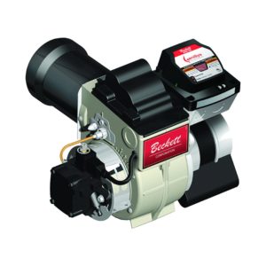
Thank you for purchasing a Beckett burner for use with your heating appliance. Please pay attention to the Safety Warnings contained within this instruction manual. Keep this manual for your records and provide it to your qualified service agency for use in professionally setting up and maintaining your burner.
Your Beckett burner will provide years of efficient operation if it is professionally installed and maintained by a qualified service technician. If at any time the burner does not appear to be operating properly, immediately contact your qualified service agency for consultation.
We recommend annual inspection/service of your heating system by a qualified service agency.
Daily – Check the room in which your burner/appliance is installed. Make sure:
Weekly
 Indicates a hazardous situation, which, if not avoided, will result in death or serious injury.
 Indicates a hazardous situation, which, if not avoided, could result in death or serious injury.
 Indicates a hazardous situation, which, if not avoided, could result in minor or moderate injury.
Within the boundaries of the hazard warning, there will be information presented describing consequences if the warning is not heeded and instructions on how to avoid the hazard.
 Intended to bring special attention to information, but not related to personal injury or property damage.
Owner’s Responsibility![]() Incorrect installation, adjustment, and use of this burner could result in severe personal injury, death, or substantial property damage from fire, carbon monoxide poisoning, soot or explosion.
Incorrect installation, adjustment, and use of this burner could result in severe personal injury, death, or substantial property damage from fire, carbon monoxide poisoning, soot or explosion.
Contact a professional, qualified service agency for the installation, adjustment and service of your oil heating system. This work requires technical training, trade experience, licensing or certification in some states and the proper use of special combustion test instruments.
Please carefully read and comply with the following instructions:
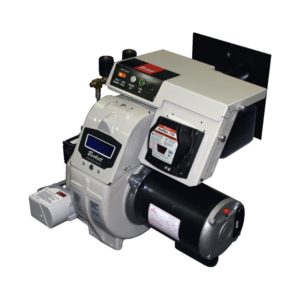
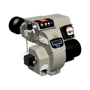
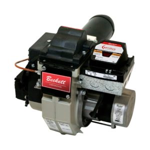
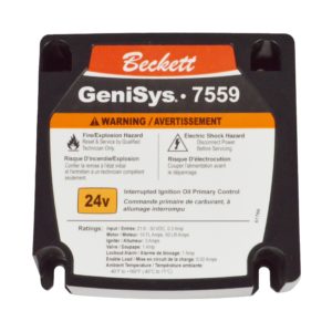
Figure 1: Burner Label Location

Do NOT Alter the Original Burner Design
Tampering with or altering the burner design could seriously impair performance, resulting in loss of static pressure, damage to the system components, reduced air volume, heavy smoke, flame impingement, appliance sooting, hot gas puff-back, and asphyxiation or fire hazards.
Maintain the design to its original configuration. Only use parts specified for the RF Burner. Do NOT operate without an air guide in the chassis or without a primary safety control installed.
Any design alteration will:
Impaired Burner Performance and Fire Hazard.
Do NOT operate the burner beyond specifications outlined in the following Table.
Frozen Plumbing and Water Damage Hazard
If the residence is unattended in severely cold weather, burner primary control safety lockout, heating system component failures, power outages or other electrical system failures could result in frozen plumbing and water damage in a matter of hours. For protection, take preventive actions such as having a security system installed that operates during power outages, senses low temperature and initiates an effective action. Consult with your heating contractor or a home security agency.
NOTICE (to the homeowner): Annual inspection/maintenance by a qualified service provider is always required. If any of the following apply, more frequent annual inspection / maintenance is required.
|
Capacity |
RF Burner: 0.38 – 3.00 GPH |
|
Certifications/ Approvals |
ANSI / UL296 and CSA – B140.0 |
|
Approved Fuels |
USA: Heating Oil – No. 1 Per ASTM D396 (S15, S500, S5000); Heating Oil – No. 2 Per ASTM D396 (S15, S500, S5000); Heating Oil – to B20 Per ASTM D396 (S15, S500, S5000); B100 Biodiesel Per ASTM D6751; Biodiesel Blends from B21-B100 made from ASTM D6751 B100 and #1 or #2 from D396; Renewable Diesel in any percentage up to R100 that meets ASTM D975. No. 2 Heating Oil. Canada: Heating Oil Types 0,1,2 Per CAN/CGSB-3.2
SEE WARNING SECTION BELOW |
|
Nominal Input Voltage |
120 VAC / 60Hz / 1 Phase |
|
Current |
5.8 Amps Maximum |
|
Motor |
Beckett p/n 21805: 1/7 HP, 3450 RPM, PSC, NEMA 48 |
|
Igniter |
Beckett p/n 51838U: Electronic Solid State rated for continuous duty. |
|
Fuel Pump |
Beckett p/n PF2032x |
|
Air Tube Combinations |
ATC Codes and selection – See Figure 3 |
|
Dimensions (Less Tube) |
Height: 10-7/8″ |
|
Operating Temperature (Note 3) |
+32°F (0°C) Minimum |
|
Environmental |
5% to 95% RH, non-condensing |
Note 1: Approval Agency listings rate these burners for 0.38 – 3.00 GPH. However, the firing rate range is limited by the specific air tube combination being used. Refer to Figure 4.
Note 2: See appliance manufacturer’s burner specifications for recommended pump discharge pressure.
Note 3: Operating temperatures above or below listed specifications must be approved by R.W. Beckett.
Use ONLY Fuels Listed for Use with this Burner
Use of unapproved fuels could result in explosion, fire, personal injury or death, and/or damage to equipment and property.
Figure 5: BTU vs. Chamber Pressure
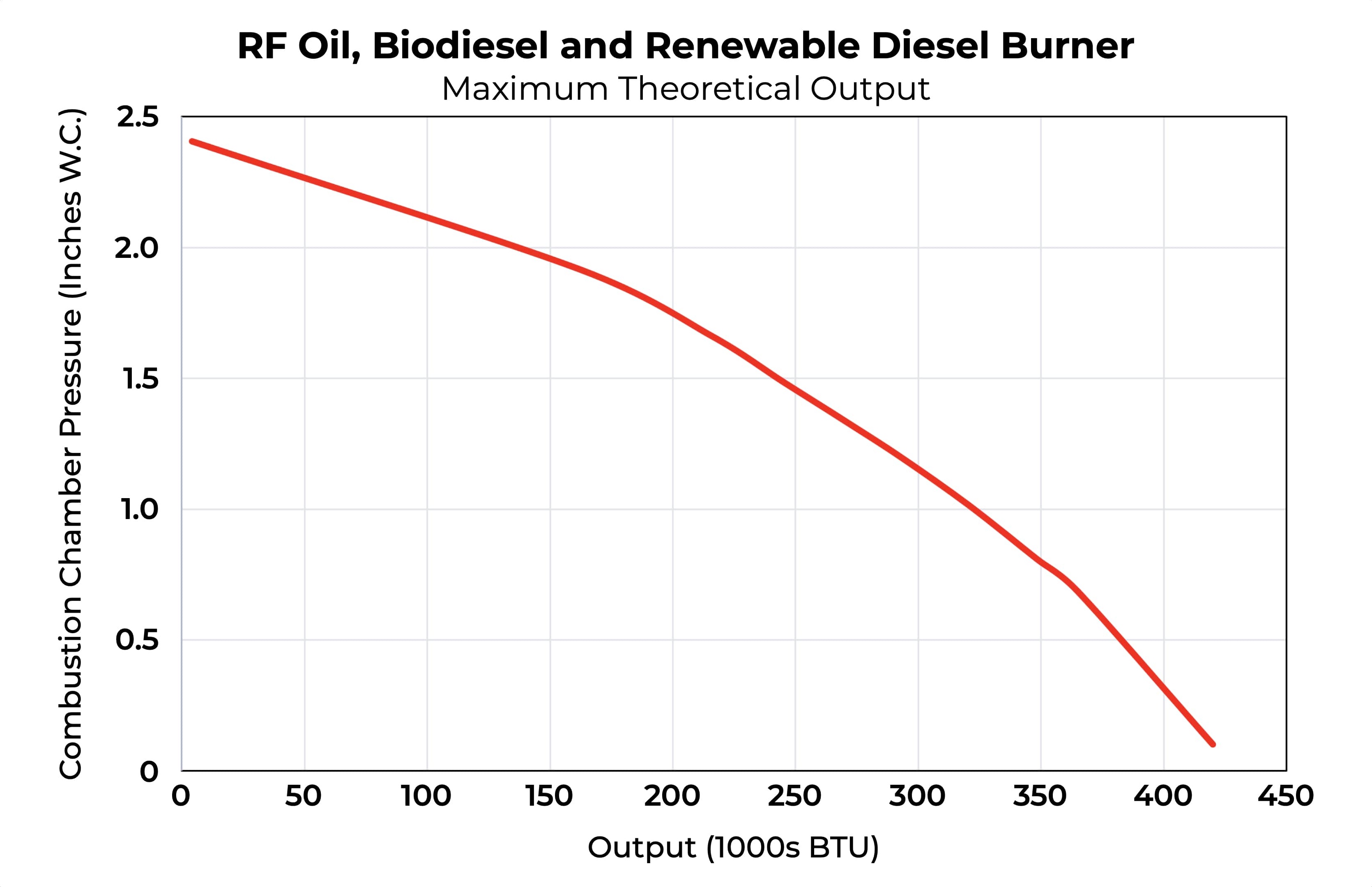
Theoretical maximum output (BTU) for given combustion chamber pressure (in.w.c.)
Special Requirements
Fuel Supply System Compatibility
The fuel supply system design and components must be compatible with the fuel being used in the appliance. Follow all guidelines and best practices recommended by the fuel supplier, NFPA 30 & NFPA 31, and any state or local ordinances for safe storage, filtering, conditioning, and delivery to the burner.
The adjustable flange and the RF burner intake cover are not intended for use with portable equipment. Contact R.W. Beckett for any non-residential applications of the RF burner.
Professional Service Required![]() Incorrect installation, adjustment, and use of this burner could result in severe personal injury, death, or substantial property damage from fire, carbon monoxide poisoning, soot or explosion.
Incorrect installation, adjustment, and use of this burner could result in severe personal injury, death, or substantial property damage from fire, carbon monoxide poisoning, soot or explosion.
Please read and understand the manual supplied with this equipment. This equipment must be installed, adjusted and put into operation only by a qualified individual or service agency that is:
The installation must strictly comply with all applicable codes, authorities having jurisdiction and the latest revision of the National Fire Protection Association Standard for the installation of Oil-burning Equipment, NFPA 31 (or CSA-B139 in Canada).
Regulation by these authorities takes precedence over the general instructions provided in this installation manual.
Fire, Smoke & Asphyxiation Hazard
Access to the 4×4 electrical box and the interior of the burner can be easily achieved by loosening (no need to remove them completely) the 2 igniter/control plate locking screws and rotating them forward. The igniter and control will now rotate back for easy access. It is not necessary to remove the igniter or control from the hinged plate unless they are being replaced.
The head position is calibrated at the factory such that the “0” setting is the full forward position. The head positioning in the RF burner is used primarily for adjusting the shape of the flame and controlling the manner in which the air mixes with the fuel. When the head is in the “0” position, nearly all of the air flows through the center of the head (near the nozzle). When the head is moved back to higher numbered positions, the amount of air that flows around the outside of the head increases. Although the head position may affect total air flow slightly, it is not meant to control the amount of excess air. That is accomplished independently with the air adjustment lever and locking screw. See Figure 6. For OEM applications the head will be set to the correct head position from the factory. If the head position needs to be adjusted to meet the appliance manufacturer’s recommendations, first loosen the igniter/control plate locking screws and then rotate the igniter control plate back to eliminate the pressure between the igniter contacts and the nozzle line electrodes. See Figure 6. Next, loosen the escutcheon plate lock screw and the spline nut and then move the escutcheon plate to the correct position as indicated by the guide bar indicator mark. See Figure 7. If no OEM head position is available, the head position should be adjusted to position “2” as a
starting point. Do not adjust the guide bar position unless the full forward position is not the “0” position.
The air adjustment for the RF is a single adjustment. Simply loosen the air adjustment locking screw (no need to remove it) and rotate the air adjustment lever to the recommended number setting in the OEM guide before beginning combustion testing. Lower numbers reduce the air, higher numbers increase the air. During final adjustment with your combustion analyzer, it is not necessary to tighten the air adjustment locking screw until the final setting is achieved.
NOTE: Always verify that the air adjustment locking screw and the 2 igniter/control plate locking screws are secured before completing the burner installation.
The RF burner is supplied with 3 air guide sizes. The default air guide is the white, midsize (2.0″) air guide. The air guide can be changed (if necessary) by removing the motor/blower wheel subassembly to gain access to the 2 screws retaining the air guide on the inside of the burner. See Figure 8. The red (1.5″) air guide will improve air adjustability for low firing rate and/or natural draft applications. The blue (2.5″) air guide will increase the available air capacity for high firing rate and/or positive pressure appliances.
The RF burner comes with a spacer installed between the motor housing and the blower wheel to assure the required 1/2″ spacing. Always re-install this spacer to assure the proper position of the blower wheel. Do not force the blower wheel against the spacer as this may cause excessive friction and higher operating amps.
The RF burner is supplied ready for ducted combustion air. If outside combustion air will be ducted to the burner, a 3″ aluminum adjustable elbow is recommended for connection to the combustion air intake. Always connect the ducting before tuning the burner because the ducting may affect the air flow to the burner and affect the settings. Refer to the temperature compensation chart, see Figure 9 for ducted combustion air. If the RF will only be using basement air for combustion, re-install the intake cover after hook-up to help prevent foreign objects from entering the intake. The intake is designed not to restrict air flow, so it will not affect your basement air settings.
The published burner ratings apply for altitudes up to 2,000 feet above sea level. For altitudes higher than 2,000 feet, apply a derating of approximately 2% per 1,000 feet. Contact R.W. Beckett for additional information.Figure 6

Figure 7

Figure 8