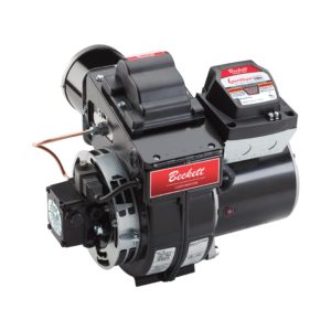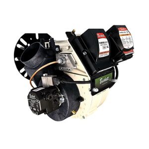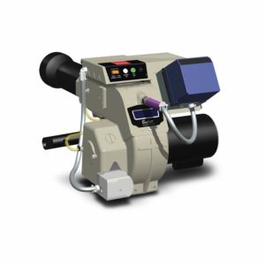
The Beckett models AF & AFG burner are designed to meet the increased demands of modern equipment and changing fuels to meet both ...
In the mid 1980’s, the design of heating products in our industry began to take on a different look. Some manufacturers were developing smaller, more efficient appliances capable of sidewall venting. These appliance configurations required certain enhanced design features in a burner. A totally new burner concept with many built-in service and performance features was required to meet today’s challenging needs. The end result was the Beckett Model AFII.
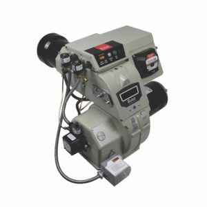
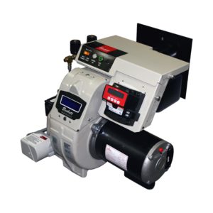
The AFII is offered in two model designations, the AFII 85 and AFII 150. The firing range of these models is .4 to .85 GPH and .75 to 1.50 GPH respectively. Each size is available for a “wet chamber” or “dry chamber” application (Figure 1 and 2).

These burners were designed for high static pressure, uniform air delivery and a smooth mix at the retention head. The air pattern developed has a helical or rifling motion to it. This preps the air for the turn it takes through the combustion head. The air also scrubs the outer air tube wall reducing temperature of the metal and forcing any oil droplets toward the point of combustion. Both burners develop their efficient air delivery utilizing an air guide and special blower wheel. The AFII 150 utilizes a “tab lock wheel” and the AFII 85 a “strip wheel”, both wheels measuring 4 1/4″ x 2″. The tab lock wheel design uses a greater amount of its blade surface to move the air and develop pressure. The air channel within the model 85 housing has a factory installed air baffle which modifies the air flow and pressure for its lower firing range. Both models have an internal “P Trap” designed into the air channel of the housing. This trap has minimized off cycle air loss through the burner to as low as 0.02%.
An air scoop, insulated to reduce sound, draws combustion air up and away from the floor. This minimizes the “infiltration” of dust, lint, and other contaminants into the burner. For air adjustment, the AFII utilizes a single, easy to adjust air control dial. If it is determined that outside combustion air is required by the burner, simply remove the inlet scoop and directly connect a 4″ duct to the housing. Do not exceed 70 total feet of run, allowing 6′ for each elbow to be installed (Figure 3).

When installing piping to outdoors, and venting into a conventional chimney, the barometric damper must be removed from the flue pipe run. The exception to this rule is when the damper will be in the same pressure zone as the air intake opening. Will it be outdoors? If not, then remove it.
The two primary air tube combinations are the model HLX (wet chamber) and the FBX (dry chamber). Both tubes have a 3-1/2″ diameter. The HLX has a recessed retention head which is step adjustable using the “stop screw” design. This combination utilizes 45-70° solid spray nozzles. The FBX has a “fixed position” retention head at the end of the air tube, and requires a 60-80° hollow or solid spray nozzle.
The primary questions you need to ask when making your selection are: What type of appliance is the burner firing into? What is the firing rate, GPH, required? How long (usable length) will the air tube be? Figure 4 shows the HLX tube and Figure 5 shows the FBX tube.
The following charts offer you information on the tubes available and their differences:
Figure 5 – The FBX air tube utilizes a head insulator. The HLX should NEVER have the front end of the air tube insulated because overheating of the steel tube and retention head could result.

It is important to check or set the “Z” dimension prior to burner installation. Whether it is factory set or done by you in the field, the “Z” dimension is a simple measurement of the position of the nozzle or retention head to the front end of the air tube or the venturi assembly. This “Z” dimension allows adjustment for the minor variances in tolerances of the manufactured parts.
To set the FBX combination, use the T-500 multi-purpose gage (Figure 6). The HLX combination sets itself. It is that simple. The HLX positions itself immediately upon reinstallation of the Nozzle Line Electrode Assembly into the air tube. All that is required for the HLX is the selection and installation of the appropriate “stop screw” into the head carrier. This stop screw automatically positions the head to the “choke” or “venturi” at the end of the air tube (Figure 7).

A total of nine stop screws is available to choose from. They vary in length by 1/16″ per pin, with the number “0” pin being the longest.
Service Tip: If you need to change the stop screw to another number, when reinstalling the Nozzle Line Electrode Assembly, you must loosen the 5/16″ screw which secures the “escutcheon plate”. This will allow the N.L.E.A. to move (forward or back) to the new position of the stop screw. Once in position, retighten the escutcheon plate screw.
The initial version of the HLX air tubes (up to April ’95) centered the retention heads (stamped HLX 6 or 9) by positioning the head support legs on the air tube choke ring or venturi. The improved version (after April ’95) incorporates three centering ribs in the choke ring. This design permits the combustion head to rest on the three centering ribs. The retention heads used in this combination are stamped AF2-6 or AF2-9. This design improvement has proved to be effective for consistently centering the head in the venturi.
NOTE: The new air tubes and head assemblies are not compatible with the original design, thus, they are not interchangeable.
For your information: The electrode replacement kit number for the HLX tube is #51484U and #51670U for the FBX combination. The kits include the electrodes, T-500 gage and the connector wires. If you need to replace the wire connectors from the transformer to the electrodes, use kit #21705U.
Service access to the nozzle line assembly has been simplified through the addition of a rear service door. The door offers quick access to the N.L.E.A. as well as cad cell assembly. Through the blue tinted “viewport” in the rear access door, it becomes easier to verify ignition and flame stability, while not running the risk of stray light interference that a clear lens would cause. Since mid-1992 the door has had a stop screw holder for storage of additional screws.
When removing the N.L.E.A. for service or inspection, follow these easy steps: open the rear service door; remove the connector tube flare and knurled nuts; remove ignition transformer quick connects from the electrodes; pull out the assembly. The 1/4″ quick connects are a “positive” connection to the ignition transformer. This design eliminates the need to move the transformer in order to service the burners.
NOTE: For those who worked on the AFII product when it was first introduced, you will notice a substantial change and improvement to the size of our electrode rod. The electrodes have been standardized as “one length fits all” up to 9″ air tube lengths. Quality push on fittings have been added at the electrode connection, along with an increase in length of transformer connector cables. “We are listening and taking action on your suggestions. We sincerely welcome your comments, so please keep them coming.”
An air scoop, insulated to reduce sound, draws combustion air up and away from the floor. This minimizes the “infiltration” of dust, lint, and other contaminants into the burner. For air adjustment, the AFII utilizes a single, easy to adjust air control dial. If it is determined that outside combustion air is required by the burner, simply
remove the inlet scoop and directly connect a 4″ duct to the housing. Do not exceed 70 total feet of run, allowing 6′ for each elbow to be installed (Figure 3).

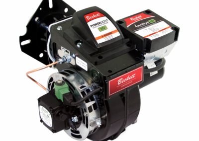
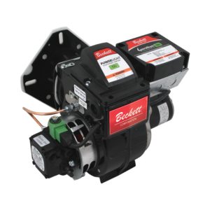
The 1/7 h.p. 3450 r.p.m. motor and fuel unit are located on one side of the burner housing. The motor is permanently lubricated, and incorporates a start switch or is capacitor start and has an automatic reset overload. The motor is specifically designed for the AFII and will not adapt to any other Beckett burners. Fuel units are single or two stage standard pumps that are interchangeable with the AF and AFG burners.
This combination is easily removed as a unit by disconnecting the motor wires, unscrewing the flare nut at nozzle line inlet, then loosening the motor mounting bolts slightly and twisting the motor so the technician-friendly “keyhole flange” is aligned to release the assembly. The fuel unit may be removed separately by unscrewing the flare nut at nozzle line inlet, and removing its two mounting bolts.
NOTE: There are two methods to gain access for cleaning or visual inspection of the blower wheel. The first is removing the inlet scoop. The second is removing the motor/fuel unit assembly. Connecting the fuel unit and motor is the drive coupling. Designed into this area is provision for oil to escape if the pump shaft seal should leak. This prevents the motor from being oil saturated and provides an indication that there is a seal leakage problem.

The designed operating pressure of the fuel delivery system on the AFII is 140 PSIG. Any variation from this will be indicated either on the burner labels, the instruction manual of the appliance manufacturer, or in the Beckett Guide to OEM Oil Specifications.
We hope that the information provided within this technical bulletin gives you greater insight into the AFII product. Contact your local distributor for product pricing, availability, or literature.
Informative and technical training resources from the leading experts in the heating industry
Have questions about our products? Looking for a solution to address a particular application? Looking to improve the overall productivity and profitability of your operation? Please don’t hesitate to reach out or schedule a no obligation, 1-on-1 consultation with a Beckett Technical Specialist — we’d love to help.
Beckett solutions are available through our network of Distributors, Independent Representatives, and Export Representatives all around the world.