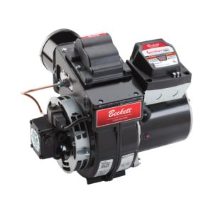
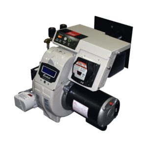
The Beckett models AF & AFG burner are designed to meet the increased demands of modern equipment and changing fuels to meet both ...
Beckett solutions are available through our network of distribution partners throughout the United States and Canada.
Beckett Regional Sales Managers provide direct sales support and product guidance across designated territories in the United States and Canada.
Beckett Independent Representatives provide Sales Support for our products throughout the United States and Canada.
Beckett solutions are available for export outside of the United States and Canada through our network of Export Representatives.

Drop us a line with any comments or questions!

Specifications for nozzles, air tube combinations, and other initial settings.

Service bulletins and product updates.

Training videos and PowerPoint presentations.

Solutions to common issues.

Look through exploded views to find the part you need.

A library of product manuals and supplemental guides.

View the limited warranty for all Beckett products.

Submit a return material authorization (RMA) Request.

Frequently asked questions, and a list of affected products.
Hands-on, practical installation, application, and operation training on Beckett’s latest products — in-person with the industry’s foremost authorities. Register today.
Informative and technical training resources from the leading experts in the heating industry — now available online, on-demand, and FREE.
Our most popular product-related instructional / training videos for the most relevant and widely seen products and applications you’ll find in the field.
For over 80 years Beckett products have been the number one choice of homeowners and contractors for their furnaces, boilers, and water heaters. As North America's foremost brand of burners, Beckett continues to provide industry leading design, reliability, and support. All backed by a comprehensive warranty program that ensures you will have years of trouble-free operation.
As North America's leading brand of burners, you can have peace of mind in using a Beckett burner on your next commercial project. With the environment in mind, we have the most comprehensive lineup of biofuel rated burners in the industry. Supported by a broad network of trained technicians, choosing a Beckett burner for your next commercial project ensures your building will have years of trouble-free operation while reducing your equipment’s impact on the environment. A return on investment for future generations.
When the sun is blazing and you're responsible for keeping Americas roads maintained, you'll want a burner that's as hard working as you are. Beckett's lineup of DC burners provides mobile heat for all types of road maintenance equipment. With their ease of service and parts availability from coast to coast, you can ensure the job gets done when the heat is on.
For over 30 years Beckett has served the pressure washer market in providing rugged yet reliable burners and components for the pressure washer industry. Our compact DC powered burners provide off-grid dependable operation in the wettest of environments. All backed by a comprehensive warranty program that ensures you will have years of trouble-free operation. So, when the "pressure" is on to get a job done, you can rely on Beckett to keep you in "hot water".
With a wide range of capacities, Beckett has served the needs of the agricultural industry for over 20 years. Our proven experience in the combustion field allows us to work with appliance engineers to ensure the strictest of parameters are met when drying organic products. Beckett's modular burner platform provides the most flexibility in applications while offering the most comprehensive lineup of biofuel rated burners in the industry. This ensures efficient reliable heat for future generations.
When freezing temperatures hit your job sites and you need dependable heat, consider Beckett for the job. From the Arctic circle to Antarctica, Beckett has proven to be the burner of choice in the harshest most remote environments. Our robust, user-friendly design provide quick maintenance and dependable operation to ensure your site stays warm.
Beckett burners and components are used in food processing applications all over the world. From bakery ovens, coffee roasters, dehydrators, and industrial process lines, Beckett robust, reliable products reduce line down time and ensure an uninterrupted output.
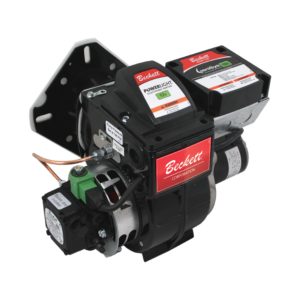
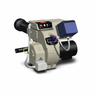
From tank to flame, Beckett delivers the most technically advanced product line in the industry — burners, igniters, controls, and accessories designed to meet the performance requirements of the industry while meeting the demands of biofuels to reduce emissions and meet carbon reduction goals. Explore all that Beckett has to offer below by selecting a brand, product category, or simply filtering through the entire product offering.
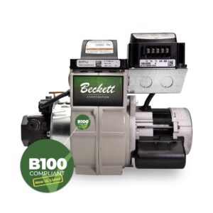
With the acquisition of Westwood Products in 2021, Beckett added depth and diversity to its already impressive catalog. In addition to the Tigerloop suite of Oil Dearaetors which has been transitioned to our Beckett branded offering, our Westwood by Beckett product offering includes fuel filters, electrodes, tank accessories, and many other HVAC service and repair items. The line includes B100 filters which, in conjunction with the Tigerloop Bio models, completes Beckett’s industry leading suite of B100 rated components from tank-to-flame and further positions as the market leader in the drive to alternative fuels.
For over 80 years Beckett products have been the number one choice of homeowners and contractors for their furnaces, boilers, and water heaters. As North America's foremost brand of burners, Beckett continues to provide industry leading design, reliability, and support. All backed by a comprehensive warranty program that ensures you will have years of trouble-free operation.
As North America's leading brand of burners, you can have peace of mind in using a Beckett burner on your next commercial project. With the environment in mind, we have the most comprehensive lineup of biofuel rated burners in the industry. Supported by a broad network of trained technicians, choosing a Beckett burner for your next commercial project ensures your building will have years of trouble-free operation while reducing your equipment’s impact on the environment. A return on investment for future generations.
When the sun is blazing and you're responsible for keeping Americas roads maintained, you'll want a burner that's as hard working as you are. Beckett's lineup of DC burners provides mobile heat for all types of road maintenance equipment. With their ease of service and parts availability from coast to coast, you can ensure the job gets done when the heat is on.
For over 30 years Beckett has served the pressure washer market in providing rugged yet reliable burners and components for the pressure washer industry. Our compact DC powered burners provide off-grid dependable operation in the wettest of environments. All backed by a comprehensive warranty program that ensures you will have years of trouble-free operation. So, when the "pressure" is on to get a job done, you can rely on Beckett to keep you in "hot water".
With a wide range of capacities, Beckett has served the needs of the agricultural industry for over 20 years. Our proven experience in the combustion field allows us to work with appliance engineers to ensure the strictest of parameters are met when drying organic products. Beckett's modular burner platform provides the most flexibility in applications while offering the most comprehensive lineup of biofuel rated burners in the industry. This ensures efficient reliable heat for future generations.
When freezing temperatures hit your job sites and you need dependable heat, consider Beckett for the job. From the Arctic circle to Antarctica, Beckett has proven to be the burner of choice in the harshest most remote environments. Our robust, user-friendly design provide quick maintenance and dependable operation to ensure your site stays warm.
Beckett burners and components are used in food processing applications all over the world. From bakery ovens, coffee roasters, dehydrators, and industrial process lines, Beckett robust, reliable products reduce line down time and ensure an uninterrupted output.
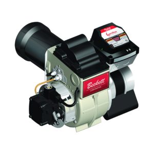
R.W. Beckett oil-fired burners were created with customer satisfaction and sustainability in mind. Our utilization of advanced components results in higher efficiency and reliability, all while reducing carbon emissions.
Our burners are suitable for a multitude of needs. They are certified for firing traditional heating oils, biodiesel blends (B100), and renewable diesel blends (R95). Truly versatile, our burners are available in AC and DC voltages and in capacities from 0.40 to 35.0 GPH. Applicable uses range from residential homes to commercial buildings, for both industrial and process installations, R.W. Beckett can meet your demands. After installation our proven burners provide years of reliable service with strong and accessible technical support.
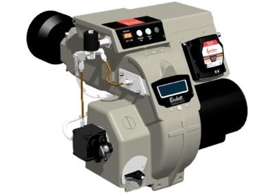
R.W. Beckett gas-fired burners were created with customer satisfaction and sustainability in mind. Our utilization of advanced components results in higher efficiency, reliability, and accessibility, all while reducing carbon emissions.
Available in capacities ranging from 250 to 5,000 MBH, our burners are suitable for a multitude of needs. Applicable uses range from residential homes to commercial, for both industrial and process installations, R.W. Beckett can meet your demands. Our burners are easy to install and service, engineered to provide years of reliable service, and backed by solid technical support and fast delivery.
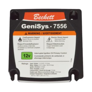
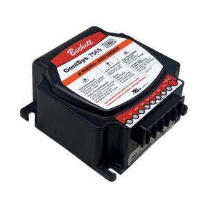
R.W. Beckett’s burner controls were created with customer satisfaction and safety in mind. Our entire suite of burner controls utilizes the most current technology to safely control the combustion process.
Available in both AC and DC voltages for off-grid applications, our controls are suitable for a multitude of needs. Our new GeniSys® model 7565 Advanced Burner Control is compatible with the myTechnician® app for modernized accessibility. The app assists with diagnostics, troubleshooting, and more. With applicable uses of our controls ranging from residential homes to commercial buildings, to process applications R.W. Beckett can meet your demands. Our multitude of models offer both fixed and programmable options and serve as a direct replacement for many competitive combustion controls.
R.W. Beckett’s boiler controls were created with customer satisfaction and sustainability in mind. The boiler control was built using Beckett’s proprietary HeatManager® algorithm which saves fuel by minimizing operating temperature, reducing energy consumption without sacrificing homeowner comfort.
Applicable to both oil and gas-fired boilers, the control is convenient for any household. With our digital display and touch pad we have made for a more intuitive experience, allowing for flexible programming of temperature limits and other settings.
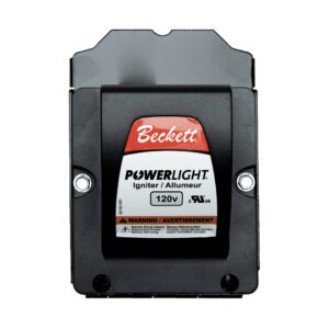
R.W. Beckett igniters were created with customer satisfaction and reliability in mind. Providing an advanced option for oil-fired burners, our Powerlight® igniter also serves as a universal replacement for other manufacturers’ igniters.
Available in a variety of AC and DC voltages for off-grid applications, our product is suitable for a multitude of needs. Designed for various applications, our igniter can be found in residential homes, commercial property, and even high-moisture environments.
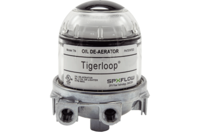
R.W. Beckett’s oil deaerators were created with customer satisfaction and efficiency in mind. With over 30 years of fine-tuning, the Tigerloop® is the most advanced oil deaerator in the world.
With its unmatched performance, Tigerloop® can handle capacities up to 50 GPH and is compatible with different heating fuels, depending on the model. The standard model is compatible with #1 and #2 heating oil and B5 Bioheat, while the Bio model accepts biofuel blends up to B100. Catering to many needs, our oil deaerator is also a safe, economical, and environmentally friendly choice for all supply systems.
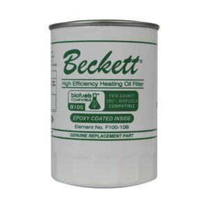
Beckett branded Spin-on filters are epoxy coated, UL Listed or UL Recognized and rated from 10 to 15 microns. Commercial Spin-on filters are rated for 52 GPH, 20 PSI, and 30 Microns. The line includes a cast aluminum tops, Filter Life Indicator (FLi™) gauge and is suitable for #1 and #2 fuel oil and rated up to B100 bio-fuels.
Westwood by Beckett canister filters feature cast iron tops and epoxy coated canisters. Element options include Classic Felt, cellulose acetate, and Classic Yarn. UL Listed/Recognized canister filters exceed GPH and pressure ratings of most competitors.
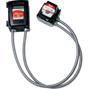
R.W Beckett’s internet connected products were created with customer satisfaction and accessibility in mind. With our modernized approach, these products can be remotely accessed through our mobile app or web browser.
Through the myTechnician® mobile app, connected products come with multiple features including troubleshooting, product programming and diagnostics. With the BeckettLink® connected tank gauge system and Wi-Fi hub, end users and oil dealers can use the Beckett Dealer Dashboard to be alerted remotely if the tank drops below predetermined levels.
For your convenience, Tank Accessories has been divided into distinct categories to help you find the products you need. Please click the links below to see all the products in each of these categories.
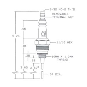
RW Beckett manufacturers hundreds of Westwood electrodes, flame rods and spark ignitors. Many are sold through distribution and additional items are available for OEM customers for special applications. RW Beckett can manufacture specialty electrodes to your specifications. The Auburn and Champion brands are also available.

Aug 4, 2017 | Burner Tutorials, Tutorials
This tutorial will guide you through the steps on using the T501 Gauge to set the electrodes and “Z” Dimensions. Click each image to view larger.

Fig. 1 — ADC or SDC Burner F Heads (side view)
To position the electrode tips in front of the face of the nozzle and above the center line, select the cross mark for the burner being serviced, DC (direct current) Fig. 1. You will be setting only one of the electrode tips.

Fig. 2 — AC Burner F Heads (side view)
AC burner F head settings are set by aligning the electrode tip with the (5/16”) cross mark shown in Fig. 2.

Fig. 3 — Tip Gap (top view)
To set the electrode tip gap (5/32”), place the gauge so that the tip is on one of the tip gap marks in Fig. 3 (top view). Adjust the remaining tip to the other mark. Bending the tips is ok if needed.

Fig. 4 — Center of Nozzle to Head Inside Diameter
To check that the nozzle is approximately centered with the head inside diameter, place the gauge in the head and note the gauge center mark location with respect to the nozzle center. Rotate the gauge and check several positions.

Fig. 5 — F Head “Z” Setting
The “Z” dimension is important because it locates the nozzle for the precise relationship with the combustion head. To set the “Z” dimension for F heads, position the gauge and loosen the nozzle line electrode assembly so that it can be moved forward or backward in the air tube until the nozzle becomes flush against the gauge. Tighten the nozzle line escutcheon plate screw to lock this “Z” dimension securely.

Fig. 6 — Tip Settings
Electrode tip setting reference chart below. See individual burner instruction manuals for more details.
| Head Style | DC F | AC F |
| Tip Gap | 5/32″ | 5/32″ |
| Tip Above Nozzle Center | 1/4″ | 5/16″ |
| Tip in Front of Nozzle | 5/32″ | 1/16″ |
Informative and technical training resources from the leading experts in the heating industry
Have questions about our products? Looking for a solution to address a particular application? Looking to improve the overall productivity and profitability of your operation? Please don’t hesitate to reach out or schedule a no obligation, 1-on-1 consultation with a Beckett Technical Specialist — we’d love to help.
Beckett solutions are available through our network of Distributors, Independent Representatives, and Export Representatives all around the world.