Firing Through-The-Door On Old Stoker Units

Aug 15, 1986 | Bulletins, Burners, General

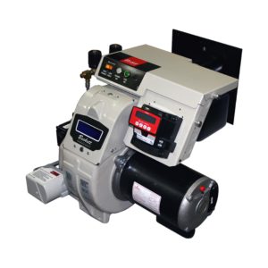
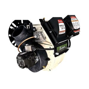
We get inquiries concerning upgrading old stoker units where the burner can be fired through the upper fire door or lower ash pit door. In this bulletin we will discuss some guidelines that will enable you to make successful retrofit applications in these older units.

Our experience has shown that retrofit can be made successfully, either by firing in the lower grate area, or through the upper feed door. The choice is yours. Use the method that works best for you.

  1. When choosing to fire through the lower section, several items must be considered:
    • Fabricate a suitable combustion chamber for the input rate. Typically, cerafelt liners are used in free-standing or blanket form.
    • Be sure to allow adequate insulation of the “mud leg” or “wet leg” portion of the boiler sections, as applicable. This can be accomplished by allowing 3-4″ of the chamber top to shield this area, or by back-filling with vermiculite pellets until this area is protected from overheating or section burn-out. (Accumulated sludge may reduce heat transfer inside the sections.)
    • Select the proper firing combination that will deliver the desired input. Usually, the best combustion results are achieved by firing the combustion head in the mid to upper range of its rated capacity. A burner such as the AFG with the F series head is well-suited for these older appliances.
    • Determine the mounting arrangement. Usually, the lower door can be modified by cutting an entry hole for the burner, then drilling and tapping holes for flange mounting. Sometimes a boiler mounting plate must be fabricated. The insertion should be 1/4″ back from flush with the inside combustion chamber wall. If a pedestal mount is utilized, it should be securely anchored to the floor or cement pad.
    • On oil applications, the nozzle spray angle and pattern should be such that no impingement is produced in the combustion area or boiler surfaces. Normally, 80° spray patterns work well in round or square chambers and 70° – 60° spray patterns are required with narrower, rectangular shapes. The flame should adequately fill the chamber without depositing carbon or soot spots.
  2. When firing through the upper feed or access door, consideration should be given to the following details:
    • Fill the lower grate area with sand or mica pellets. Bring this level of material upward until it is within the recommended distance below the nozzle centerline. See Chart and Figures below.Recommended minimum inside dimensions of refractory-type combustion chambers.
      1 Firing Rate (GPH) 2 Length (L) 3 Width (W) 4 Dimension (C) 5 Suggested Height (H) 6 Minimum Dia. Vertical Cyl.
      0.50 8 7 4 8 8
      0.65 8 7 4.5 9 8
      0.75 9 8 4.5 9 9
      0.85 9 8 4.5 9 9
      1.00 10 9 5 10 10
      1.10 10 9 5 10 10
      1.25 11 10 5 10 11
      1.35 12 10 5 10 11
      1.50 12 11 5.5 11 12
      1.65 12 11 5.5 11 13
      1.75 14 11 5.5 11 13
      2.00 15 12 5.5 11 14
      2.25 16 12 6 12 15
      2.50 17 13 6 12 16
      2.75 18 14 6 12 18

    Notes

    664810

    • Flame lengths are approximately as shown in column (2). Often, tested boilers or furnaces will operate well with chambers shorter than the lengths shown in column (2). As a general practice, any of these dimensions can be exceeded without much effect on combustion.
    • “A” = Usable air tube length. The burner head should be 1/4″ back from the inside wall of the combustion chamber. Under no circumstances should the burner head extend into the combustion chamber. If chamber opening is in excess of 4-3/8″, additional set back may be required.
    • Modify the feed door to accept the burner and mounting flange. Be sure the boiler crown sheet is at least two times as high above the nozzle centerline as it is from the nozzle centerline to the “floor”.
    • A soft refractory blanket should be installed to cover the “floor” of the new chamber area. Generally, this blanket is adequate to help radiate heat back into the flame envelope and to help vaporize the oil droplets for a cleaner, shorter flame. Should the flame impinge on the back wall, or if the smoke level cannot be cleaned up, then a target wall or cerafelt should be installed.
    • When selecting a burner with a broad-based flame, such as a Beckett burner, generally speaking, 70°-80° solid nozzles will perform well in these boiler applications. (See item “e” above.)
    • Seal all cracks and sectional gaps with suitable retort cement so that combustion tests will not be diluted by infiltration air.
    • When adjusting the oil burner, we recommend the following criteria be used:
      1. Set the barometric regulator to maintain -.01 to -.02″ W.C. over-fire draft.
      2. Adjust the air until a trace of smoke is found.
      3. Measure the CO2 or O2% at the trace of smoke level. Example, 13.0% CO2 (3.5% O2).
      4. Increase the air until the CO2 has been reduced to 12.0% (4.5% O2). This is a built in “cushion” to accommodate variables in fuel, draft, viscosity and other adverse conditions.
      5. Measure the gross stack temperature at steady-state operation. For these older units, a stack temperature range from 450° – 700°F is typical. Higher than 700° may require derating the input, or baffling, while under 450° could signify slight under-firing. Also, lower stack temperatures (under 350°F) may lead to condensation problems during the initial start up and heavy load condition.

    Keeping these considerations in mind will help you in your application work. Many experienced contractors have made installations in the manner described here, and they have been able to achieve fine results.

Beckett Training is Now Online

Informative and technical training resources from the leading experts in the heating industry

We're Here to Help!

Have questions about our products? Looking for a solution to address a particular application? Looking to improve the overall productivity and profitability of your operation? Please don’t hesitate to reach out or schedule a no obligation, 1-on-1 consultation with a Beckett Technical Specialist — we’d love to help.

Where to Buy

Beckett solutions are available through our network of Distributors, Independent Representatives, and Export Representatives all around the world.