


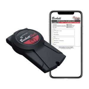
This Quick Tutorial Will Guide you Through The Steps on Installing the Rocket Wireless Fuel Level Monitor
Begin by determine the total tank height either by making a direct measurement or use the chart in the troubleshooting section in this module.

Once the tank height is determined, use the chart in the troubleshooting section of this module to locate the correct DIP switch setting for your tank. The row of DIP switches is located on the back of the Receiver Display. Toggling an individual switch up towards the antenna will put it into the “ON” position.

Install the supplied metal adapter into an unused 2” NPT opening in the top of the tank. Apply pipe sealant on the Adapter threads and tighten appropriately. Do not install the transmitter at this time.

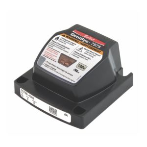
On the Receiver and Transmitter there are black dots located on the side of each device. To synchronize, plug the Receiver Display into a convenient 120 VAC electrical outlet.

The LCD display on the Receiver will show a flashing top bar (for about 2 minutes)

During this 2 minute “Learn” period, slide the Transmitter, starting at the bottom of the right side of the Receiver until the black dots touch each other or until the Receiver Display bars begin to increase in size.
Keep the devices in that position for about 20 seconds or until all ten bars flash and a short “beep” occurs to indicate that synchronization is complete.

The Transmitter stays in “Fast” transmit mode for 10 minutes following synchronization. Moving the Transmitter up and down above a solid surface should decrease or increase the number of bars respectively on the Receiver Display. If you wish to deactivate “Fast” transmit mode, again slide the Transmitter dot towards or past the Receiver dot.

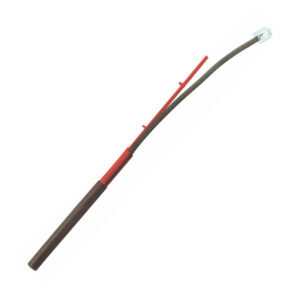
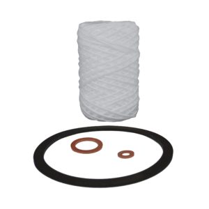
Now fasten the Transmitter to the Adapter using the gasket and screws provided. Do not over tighten.

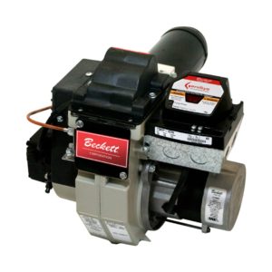
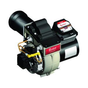
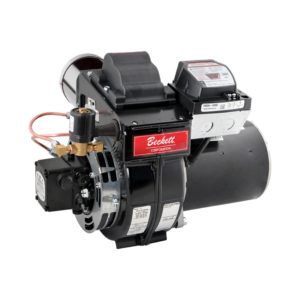
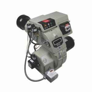
The Rocket 17000 system uses ultrasonic radio wave technology to measure the fuel level in the tank. It then uses wireless transmission to send the measured fuel level to the Receiver

Troubleshooting Tips and Dip Switch Setting Chart


Installation


DISPLAY CONTAINS FLASHING TRIANGLE—NO BARS DISPLAYED
Indicates that the receiver has not received a signal for two hours. Possible causes are:
- Receiver not matched to transmitter—Resynchronize
- Receiver location not suitable—Relocate receiver
- Failed Battery—Replace Battery (use 3 Volt CR2430)
- Moisture inside Transmitter (broken seal)—Replace Rocket sensor.

DISPLAY CONTAINS FLASHING TRIANGLE—
MIDDLE BAR DISPLAYED
Indicates that the Transmitter is not receiving an echo from its ultrasonic signal inside the tank. Likely cause:
Condensation on the sensing surface at the bottom of the Transmitter. Allow time to dry. If condition persists, remove Transmitter from the tank and clean sensor surface and verify that the seal is undamaged.
